Infiniti F50. Manual — part 177
NAVIGATION SYSTEM
AV-73
C
D
E
F
G
H
I
J
L
M
A
B
AV
Terminals and Reference Value for AV and NAVI Control unit
EKS001LT
Terminal No.
(Wire color)
Item
Signal
input/
output
Condition
Voltage
Example of
symptom
+
–
Ignition
switch
Operation
1 (B)
Ground
Ground
-
ON
-
Approx. 0 V
-
2 (SB)
Ground
Battery
power
Input
OFF
-
Battery voltage
System does not
work properly.
3 (SB)
4 (B)
Ground
Ground
-
ON
-
Approx. 0 V
-
6 (L/OR)
Ground
ACC signal
Input
ACC
-
Battery voltage
System does not
work properly.
7 (R)
8 (L)
voice guide
signal
Output
ON
Press the “voice”
switch.
Only route guide
and operation
guide are not
heard.
9
-
Shield
ground
-
-
-
-
-
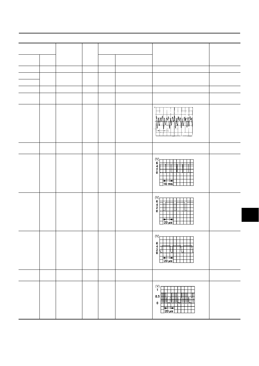
11 (R)
14
Vertical syn-
chronizing
(VP) signal
Input
ON
-
Superimposed
screen is rolling.
12 (B)
14
RGB area
(YS) signal
Output
ON
Press the “info”
switch.
RGB screen is
not shown.
13 (W)
14
Horizontal
synchroniz-
ing (HP) sig-
nal
Input
ON
Select “ Rearview”
in “Confirmation/
Adjustment Mode”
mode and display
the rearview picture
on the screen.
RGB screen is
not shown.
14
Shield
ground
RGB Ground
-
ON
-
Approx. 0 V
-
15 (LG)
19
RGB signal
(B: blue)
Output
ON
Select “SCREEN
ADJUSTMENT” of
Confirmation/Adjust-
ment Mode function.
RGB screen
looks yellowish.
SKIA0171J
SKIA0161E
SKIA0162E
SKIA0163E
SKIA0167E
AV-74
NAVIGATION SYSTEM
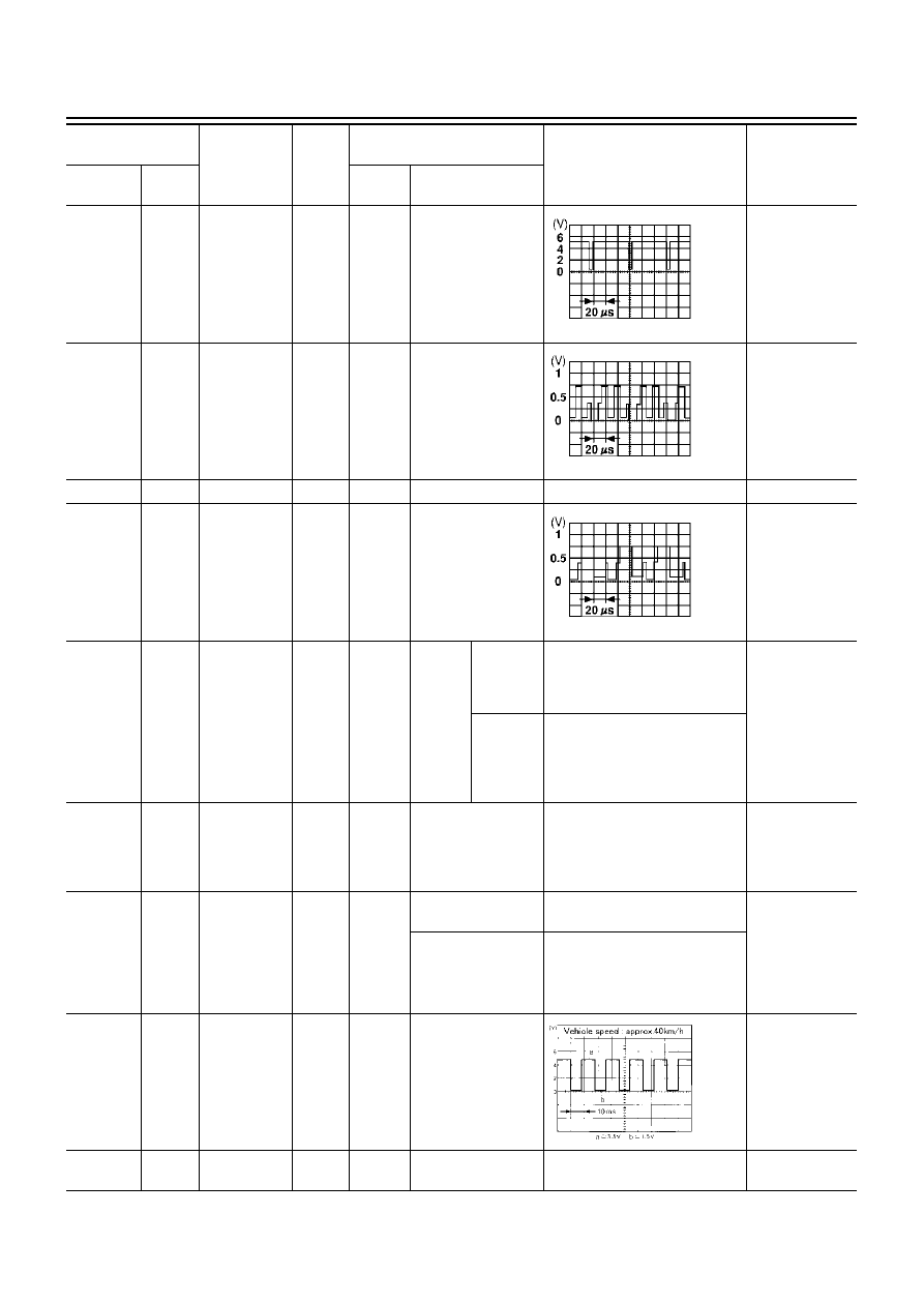
16 (G)
14
RGB syn-
chronizing
signal
Output
ON
Press the “MAP”
switch.
RGB screen is
rolling.
18 (L)
19
RGB signal
(R: red)
Output
ON
Select “SCREEN
ADJUSTMENT” of
Confirmation/Adjust-
ment Mode function.
RGB screen
looks bluish.
19
-
RGB ground
-
-
-
-
-
21 (PU)
19
RGB signal
(G: green)
Output
ON
Select “SCREEN
ADJUSTMENT” of
Confirmation/Adjust-
ment Mode function.
RGB screen
looks reddish.
25 (R/L)
Ground
Illumination
control signal
Input
ON
Light-
ing
switch
ON
(posi-
tion 1)
Optical
sensor is
exposed
to light.
Approx. 3.5V or more
Screen does not
switch between
daytime mode
and nighttime
mode.
Optical
sensor is
not
exposed
to light.
Approx. 1.5V or less
26 (W/G)
Ground
Ignition signal
Input
ON
-
Battery voltage
A/C operation is
not possible.
Vehicle informa-
tion setting is not
possible.
27 (R/B)
Ground
Reverse sig-
nal
Input
ON
AT selector lever in
R-position
Battery voltage
The navigation
current-location
mark moves
strangely when
the vehicle is
moving back-
wards.
AT selector lever not
in R-position
Approx. 3.0V or less
28 (OR/L)
Ground
Vehicle
speed signal
(8-pulse)
Input
ON
When vehicle speed
is approx. 40 km/h
(25 MPH)
Navigation cur-
rent-location
mark does not
indicate the cor-
rect position.
31
-
Shield
ground
-
-
-
-
-
Terminal No.
(Wire color)
Item
Signal
input/
output
Condition
Voltage
Example of
symptom
+
–
Ignition
switch
Operation
SKIA0164E
SKIA0165E
SKIA0166E
SKIA0168E
NAVIGATION SYSTEM
AV-75
C
D
E
F
G
H
I
J
L
M
A
B
AV
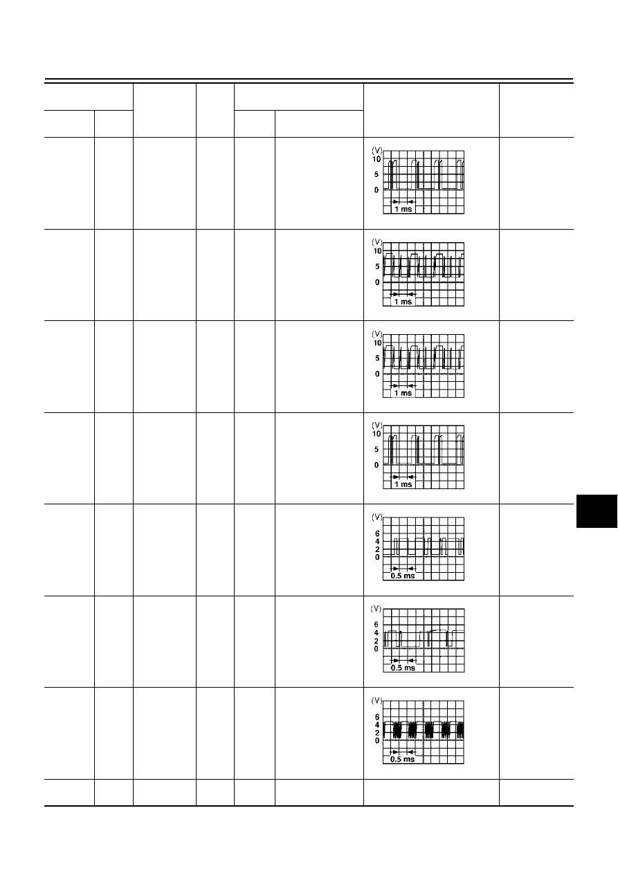
32 (PU)
Ground
Communica-
tion signal
(ME-AV)
Input
ON
Perform various set-
tings on the vehicle
information screen.
Clock cannot be
adjusted.
Vehicle informa-
tion screen is
not shown.
33 (LG)
Ground
Communica-
tion signal
(AV-ME)
Output
ON
Display the vehicle
information screen.
Clock cannot be
adjusted.
Vehicle informa-
tion screen is
not shown.
34 (P)
Ground
CONSULT-II
communica-
tion signal
(AV-CN)
Output
ON
Perform CONSULT-
II.
Diagnosis with
CONSULT-II is
not possible.
35 (BR/Y)
Ground
CONSULT-II
communica-
tion signal
(CN-AV)
Input
ON
Perform CONSULT-
II.
Diagnosis with
CONSULT-II is
not possible.
37 (W)
Ground
A/C commu-
nication sig-
nal (AC-AV)
Input
ON
-
A/C status is not
indicated cor-
rectly.
38 (R)
Ground
A/C commu-
nication sig-
nal (AV-AC)
Output
ON
-
A/C operation is
not possible.
39 (B)
Ground
A/C clock sig-
nal
Input
ON
-
A/C status is not
indicated cor-
rectly.
43
-
Shield
ground
-
-
-
-
-
Terminal No.
(Wire color)
Item
Signal
input/
output
Condition
Voltage
Example of
symptom
+
–
Ignition
switch
Operation
SKIA0170E
SKIA0169E
SKIA0169E
SKIA0170E
SKIA0173E
SKIA0172E
SKIA0174E
AV-76
NAVIGATION SYSTEM
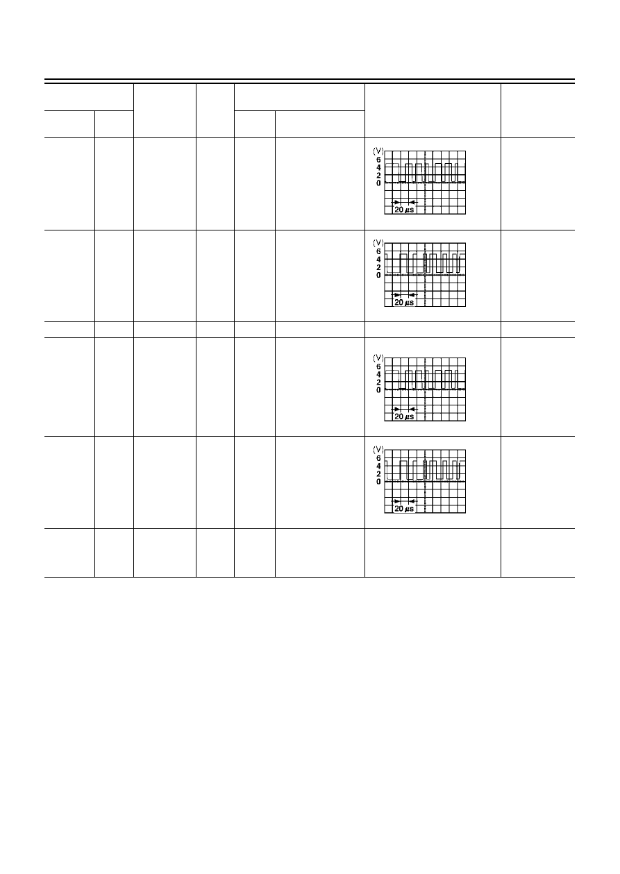
44 (Y)
Ground
Communica-
tion signal (+)
Input/
output
ON
-
System does not
work properly.
45 (BR)
Ground
Communica-
tion signal (-)
Input/
output
ON
-
System does not
work properly.
46
-
Shield
-
-
-
-
-
47 (LG)
Ground
Communica-
tion signal (+)
Input/
output
ON
-
System does not
work properly.
48 (PU)
Ground
Communica-
tion signal (-)
Input/
output
ON
-
System does not
work properly.
66
67
GPS signal
Input
ON
Connector is not
connected.
Approx. 5 V
Navigation sys-
tem GPS correc-
tion is not
possible.
Terminal No.
(Wire color)
Item
Signal
input/
output
Condition
Voltage
Example of
symptom
+
–
Ignition
switch
Operation
SKIA0175E
SKIA0176E
SKIA0175E
SKIA0176E
Нет комментариевНе стесняйтесь поделиться с нами вашим ценным мнением.
Текст