Infiniti F50. Manual — part 158
REFRIGERANT LINES
ATC-157
C
D
E
F
G
H
I
K
L
M
A
B
ATC
CHECKING PROCEDURE
To prevent inaccurate or false readings, make sure there is no refrigerant vapor, shop chemicals, or cigarette
smoke in the vicinity of the vehicle. Perform the leak test in calm area (low air/wind movement) so that the
leaking refrigerant is not dispersed.
1.
Turn engine OFF.
2.
Connect a suitable A/C manifold gauge set to the A/C service ports.
3.
Check if the A/C refrigerant pressure is at least 345 kPa (3.52 kg/cm
2
, 50 psi) above 16
°
C (61
°
F). If less
than specification, recover/evacuate and recharge the system with the specified amount of refrigerant.
NOTE:
At temperatures below 16
°
C (61
°
F), leaks may not be detected since the system may not reach 345 kPa (3.54
kg/cm
2
, 50 psi).
4.
Conduct the leak test from the high side (compressor discharge a to evaporator inlet f) to the low side
(evaporator drain hose g to shaft seal h). Refer to
. Perform a leak check for the
following areas carefully. Clean the component to be checked and move the leak detection probe com-
pletely around the connection/component.
Compressor
Check the fitting of high and low pressure hoses, relief valve and shaft seal.
Liquid tank
Check the refrigerant pressure sensor.
Service valves
Check all around the service valves. Ensure service valve caps are secured on the service valves (to pre-
vent leaks).
NOTE:
After removing A/C manifold gauge set from service valves, wipe any residue from valves to prevent any
false readings by leak detector.
Cooling unit (Evaporator)
With engine OFF, turn blower fan on
″
High
″
for at least 15 seconds to dissipate any refrigerant trace in the
cooling unit. Wait a minimum of 10 minutes accumulation time (refer to the manufacturer
′
s recommended
procedure for actual wait time) before inserting the leak detector probe into the drain hose.
Keep the probe inserted for at least 10 seconds. Use caution not to contaminate the probe tip with water
or dirt that may be in the drain hose.
5.
If a leak detector detects a leak, verify it at least once by blowing compressed air into area of suspected
leak and repeating the check as outlined above.
6.
Do not stop when one leak is found. Continue to check for additional leaks at all system components.
If no leaks are found, perform steps 7 - 10.
7.
Start engine.
8.
Set the heater A/C control as follows;
a.
AUTO switch: ON
b.
Face mode
c.
Intake position: Recirculation
d.
Max cold temperature
e.
Fan speed: High
9.
Run engine at 1,500 rpm for at least 2 minutes.
10. Turn engine off and perform leak check again by following steps 4 through 6 above.
ATC-158
REFRIGERANT LINES
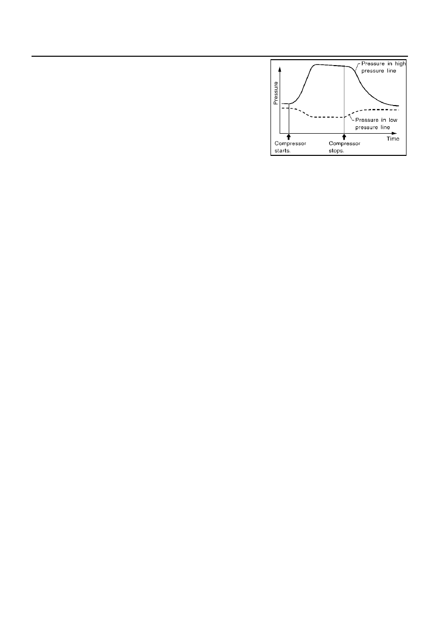
Refrigerant leaks should be checked immediately after stopping the
engine. Begin with the leak detector at the compressor. The pres-
sure on the high pressure side will gradually drop after refrigerant
circulation stops and pressure on the low pressure side will gradually
rise, as shown in the graph. Some leaks are more easily detected
when pressure is high.
11. Before connecting ACR4 to vehicle, check ACR4 gauges. No refrigerant pressure should be displayed. If
pressure is displayed, recover refrigerant from equipment lines and then check refrigerant purity.
12. Confirm refrigerant purity in supply tank using ACR4 and refrigerant identifier.
13. Confirm refrigerant purity in vehicle A/C system using ACR4 and refrigerant identifier.
14. Discharge A/C system using approved refrigerant recovery equipment. Repair or replace the leaking fit-
ting or component as necessary.
15. Evacuate and recharge A/C system and perform the leak test to confirm there are no remaining refrigerant
leaks.
16. Conduct A/C performance test to ensure system works properly.
SHA839E

SERVICE DATA AND SPECIFICATIONS (SDS)
ATC-159
C
D
E
F
G
H
I
K
L
M
A
B
ATC
SERVICE DATA AND SPECIFICATIONS (SDS)
PFP:00030
Compressor
EJS001QE
Lubricant
EJS001QF
Refrigerant
EJS001QG
Engine Idling Speed
EJS001QH
Refer to
EC-698, "Idle Speed and Ignition Timing"
Belt Tension
EJS001QI
Refer to
.
Model
Calsonic Kansei V-6
Type
V-6 variable displacement
Displacement
cm
3
(cu in)/rev
Max.
184 (11.228)
Min.
14.5 (0.885)
Cylinder bore
×
stroke
mm (in)
37 (1.46)
×
[2.3 - 28.6 (0.091 - 1.126)]
Direction of rotation
Clockwise (viewed from drive end)
Drive belt
Poly V
Model
Calsonic Kansei V-6
Name
Nissan A/C System Oil Type S
Part number
KLH00-PAGS0
Capacity
m
(US fl oz, lmp fl oz)
Total in system
180 (6.0, 6.3)
Compressor (Service part) charg-
ing amount
180 (6.0, 6.3)
Type
HFC-134a (R-134a)
Capacity
kg (lb)
0.60 (1.32)
ATC-160
SERVICE DATA AND SPECIFICATIONS (SDS)
Нет комментариевНе стесняйтесь поделиться с нами вашим ценным мнением.
Текст