Infiniti F50. Manual — part 15

WIRING DIAGRAM
ACS-53
[ICC]
C
D
E
F
G
H
I
J
L
M
A
B
ACS
TKWM0449E
ACS-54
[ICC]
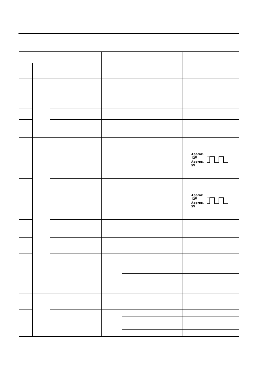
TERMINALS AND REFERENCE VALUE
TERMINALS AND REFERENCE VALUE
PFP:00000
Terminals and Reference Value for ICC Unit
EKS003P3
TERMINALS
(WIRE COLOR)
ITEM
CONDITION
VOLTAGE (V)
+
-
IGNI-
TION
SWITCH
OPERATION
1(P)
2(P)
Ground
Battery power supply
OFF
—
Power supply voltage (Approx.
12)
4
(L/W)
Wiper motor HI signal
ON
Wiper HI operating
Approx. 0
Wiper HI not operating
Power supply voltage (Approx.
12)
5
(P/B)
CAN L
ON
—
—
6 (L)
Release switch power supply
ON
—
Approx. 10
8
(PU)
24
(OR)
Brake pressure sensor power
supply
ON
—
Approx. 5
10
(W/R)
Ground
Brake booster solenoid
(+) side
ON
—
12
(B/R)
Brake booster solenoid
(–) side
ON
—
13
(L/Y)
Wiper motor LO signal
ON
Wiper LO operating
Approx. 0
Wiper LO not operating
Power supply voltage (Approx.
12)
14
(LG/
B)
CAN H
ON
—
—
15
(P)
Brake release switch
(normal closed)
ON
Depress the brake pedal.
Approx. 0
Release the brake pedal.
Approx. 10
17
(B/Y)
24
(OR)
Brake pressure sensor signal
ON
Release the brake pedal.
Approx. 0.5
Depress the brake pedal.
Approx. 0.5 - 5
(Note) Voltage becomes higher
depending on effectiveness of
depressing brakes.
19(G)
20(B)
46(B)
Ground
Ground
ON
—
Approx. 0
21(Y)
ICC warning chime
ON
Activated
Approx. 0 - 12
Not activated
Approx. 12
22
(R/B)
Brake release switch
(normally open)
ON
Depress the brake pedal.
Approx. 10
Release the brake pedal.
Approx. 0
SKIA1243E
SKIA1243E

TERMINALS AND REFERENCE VALUE
ACS-55
[ICC]
C
D
E
F
G
H
I
J
L
M
A
B
ACS
25
(PU/
W)
Ground
ICC system warning lamp
signal
ON
When warning lamp is ON
Approx. 0
When warning lamp is OFF
Power supply voltage (Approx.
12)
29(G)
ICC brake switch (normal
closed)
ON
Selector
lever: Not in
“N” or “P”
position
Depress the brake
pedal.
Approx. 0
Release the brake
pedal.
Power supply voltage (Approx.
12)
33(W
/G)
42(W
/G)
Ignition switch ON or START
ON
—
Battery voltage (Approx.12)
38
(R/W)
Stop lamp switch
(normally open)
ON
Depress the brake pedal.
Battery voltage (Approx.12)
Release the brake pedal.
Approx. 0
40
(Y/R)
Parking brake signal
ON
Parking brake is ON
Power supply voltage (Approx.
12)
Parking brake is OFF
Approx. 0
47
(L/W)
Stop lamp drive output signal
ON
Brake operating with ICC system
Battery voltage (Approx.12)
Brake not operating with ICC sys-
tem
Approx. 0
49
(B/Y)
58
(GY/L)
ICC steering switch signal
ON
When ON/OFF switch is pressed
Approx. 0
When CANCEL switch is pressed
Approx. 1.1
When DISTANCE adjusting switch
is pressed
Approx. 2.1
When COAST/SET switch is
pressed
Approx. 2.9
When ACCELERATE/RESUME
switch is pressed
Approx. 3.6
When no switch is pressed
Approx. 4.2
57(R)
Ground
Vacuum motor/air valve/
release valve output signal
ON
Being controlled
Power supply voltage (Approx.
12)
59
(OR/
G)
A/T OD cancel signal
ON
When O/D is canceled
Approx. 2 or less
O/D
Approx. 5 - 10
67
(R/W)
Cruise output signal
ON
Being controlled
Approx. 8
Not controlled
Approx. 0
69
(R/Y)
68
(B)
Throttle opening angle signal
ON
When accelerator pedal is fully
released
Approx. 0.5
When accelerator pedal is fully
depressed
Approx. 4.0
70
(Y/B)
Ground
Release valve signal
ON
When motor is not driving
Power supply voltage (Approx.
12)
When motor is driving
Approx. 0
71
(G/Y)
Air valve signal
ON
When motor is not driving
Power supply voltage (Approx.
12)
When motor is driving
Approx. 0
TERMINALS
(WIRE COLOR)
ITEM
CONDITION
VOLTAGE (V)
+
-
IGNI-
TION
SWITCH
OPERATION

ACS-56
[ICC]
TERMINALS AND REFERENCE VALUE
Terminals and Reference Value for ICC Sensor
EKS003P4
Terminals and Reference Value for ICC Warning Chime
EKS003P5
72
(L/R)
Ground
Vacuum motor signal
ON
When motor is not driving
Power supply voltage (Approx.
12)
When motor is driving
Approx. 0
TERMINALS
(WIRE COLOR)
ITEM
CONDITION
VOLTAGE (V)
+
-
IGNI-
TION
SWITCH
OPERATION
TERMINALS
(WIRE COLOR)
ITEM
CONDITION
VOLTAGE (V)
+
–
IGNI-
TION
SWITCH
OPERATION
1
(Y/R)
Ground
ICC sensor power
ON
—
Battery voltage (Approx.12)
3
(LG/B)
CAN H
ON
—
—
6
(P/B)
CAN L
ON
—
—
4(B)
Ground
ON
—
Approx. 0
TERMI-
NALS
(WIRE
COLOR)
ITEM
CONDITION
VOLTAGE(V)
IGNI-
TION
SWITCH
OPERATION
1
(BR/W)
Ignition switch ON or
START
ON
—
Power supply voltage (Approx.
12)
2
(Y)
ICC warning signal
ON
Chime output OFF
Approx. 12
Chime output ON
Approx. 0 - 12
Нет комментариевНе стесняйтесь поделиться с нами вашим ценным мнением.
Текст