Infiniti F50. Manual — part 258

BRAKE MASTER CYLINDER
BR-13
C
D
E
G
H
I
J
K
L
M
A
B
BR
BRAKE MASTER CYLINDER
PFP:46010
Components
EFS0020U
Removal and Installation
EFS0020V
REMOVAL
1.
Drain brake fluid.
2.
Remove the harness connectors for the fluid level sensor and pressure sensor.
3.
Using a flare nut wrench, remove the brake tube from the master cylinder.
4.
Remove the mounting nuts, and remove the master cylinder assembly from the vehicle.
INSTALLATION
CAUTION:
●
Refill with new brake fluid “DOT3”.
●
Never reuse drained brake fluid.
1.
Temporarily tighten the flare nuts on the brake tube to master cylinder by hand.
2.
Install the master cylinder to the brake booster assembly, and tighten the mounting nuts to the specified
torque.
1.
Reservoir cap
2.
Oil filter
3.
Reservoir tank
4.
Seal
5.
Piston stopper
6.
Pin
7.
Cylinder body
8.
O-ring
9.
Piston stopper
10. Pressure sensor
11.
O-ring
12.
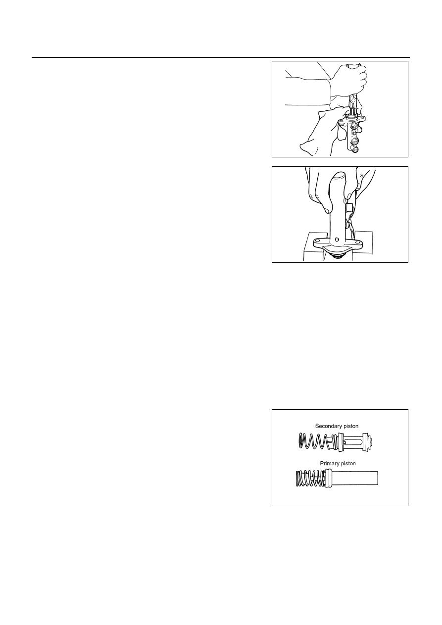
Secondary piston assembly
13. Primary piston assembly
14. Plate
15.
Guide assembly
16. Plate
(Not inserted in some vehicles.)
17. Snap-ring
SFIA0894E

BR-14
BRAKE MASTER CYLINDER
CAUTION:
●
Do not damage and stain the rod of the primary piston.
●
Do not reuse the O-ring seal, and primary piston.
●
Apply silicon grease for the O-ring seal and primary pis-
ton.
3.
Using a flare nut torque wrench, tighten the flare nut on the brake tube to the specified torque.
4.
Refill the new brake fluid and bleed air. Refer to
BR-10, "Bleeding Brake System"
Disassembly and Assembly
EFS0020W
DISASSEMBLY
Models without ICC
1.
Tighten the flange of the cylinder body in base in the figure.
CAUTION:
●
Pay attention to the orientation of master cylinder body.
●
Use the copper plate or closes for fixing the body in the
vise.
2.
Using the pin-punch (commercial service tool: dia approx.
4mm), remove pin form the reservoir tank.
3.
Remove the master cylinder assembly from the vise.
4.
Remove the reservoir tank and grommet from the cylinder body.
5.
Push the primary piston and remove the stopper pin from sec-
ondary tank boss hole in the cylinder body.
CAUTION:
Be careful not to damage the inner wall of the cylinder.
NBR386
: 15 - 17 N·m (1.5 - 1.8 kg-m, 11 - 12 ft-lb)
BRA0558D
BRA0559D
BRA0560D

BRAKE MASTER CYLINDER
BR-15
C
D
E
G
H
I
J
K
L
M
A
B
BR
6.
Remove the snap ring in pushing primary piston.
CAUTION:
Be careful not to put out the piston.
7.
Holding the rod of the primary piston, remove the primary piston
assembly, the plate and the guide with pulling straight to prevent
the cup from being caught by the inner wall of the cylinder.
8.
Remove the plate and the guide from the primary piston.
CAUTION:
Be careful not to damage the rod from the inner wall of the
plate.
9.
Tap the flange using a soft block such as wood, and carefully
pull the secondary piston assembly straight out to prevent the
inner wall of the cylinder from being damaged.
Models with ICC
CAUTION:
Be careful not to damage the rod of primary piston with covering cloths in acting.
1.
Tighten the flange of the cylinder body in base in the figure.
CAUTION:
●
Pay attention to the orientation of master cylinder body.
●
Use the copper plate or closes for fixing the body in the
vise.
2.
Push the primary piston and remove the piston stopper from
secondary tank boss hole in the cylinder body.
CAUTION:
Be careful not to damage the inner wall of the cylinder.
BRA0561D
BRA0033D
BRA0558D
SFIA0997E
BR-16
BRAKE MASTER CYLINDER
3.
Remove the snap ring in pushing primary piston.
CAUTION:
Be careful not to put out the piston.
4.
Holding the rod of the primary piston, remove the primary piston
assembly, the plate and the guide with pulling straight to prevent
the cup from being caught by the inner wall of the cylinder.
5.
Remove the plate and the guide from the primary piston.
CAUTION:
Be careful not to damage the rod from the inner wall of the
plate.
6.
Tap the flange using a soft block such as wood, and carefully
pull the secondary piston assembly straight out to prevent the
inner wall of the cylinder from being damaged.
7.
Remove the reservoir tank.
CAUTION:
Remove the reservoir tank only when necessary.
INSPECTION AFTER DISASSEMBLY
Inspect the next items.
Master Cylinder
●
Check the inner wall of the cylinder for damage, wear, corrosion, and pin holes. Replace the cylinder if a
malfunction is detected.
ASSEMBLY
CAUTION:
●
Never use mineral oils such as kerosene or gasoline during the cleaning and assembly processes.
●
Make sure that there is no foreign material such as dirt and dust on the inner wall of the cylinder,
piston, and cup seal. Be careful not to damage the parts with a service tool when assembling.
●
Do not drop the parts. Do not use any dropped parts.
Models without ICC
1.
Apply brake fluid to the inner wall of cylinder body and contact surface of the piston assembly.
2.
Insert secondary piston and primary piston assembly into cylin-
der body in this order.
CAUTION:
●
Do not reuse the primary and secondary piston assem-
blies.
●
Pay attention to the orientation of the piston cup, and
insert straight to prevent the cup from being caught by
the inner wall of the cylinder.
●
Always replace the inner kit as an assembly.
BRA0561D
BRA0561D
BRA0033D
SFIA0788E
Нет комментариевНе стесняйтесь поделиться с нами вашим ценным мнением.
Текст