Infiniti F50. Manual — part 215

FRONT DOOR LOCK
BL-107
C
D
E
F
G
H
J
K
L
M
A
B
BL
5.
Disconnect the interior handle cable and locking knob cable
from the back side of the front door finisher.
6.
Reach to separate the key cylinder rod and exterior handle rod connection (on the handle).
7.
Remove the mounting screws (TORX T30), remove the door
lock assembly.
8.
Disconnect the door lock actuator connector.
9.
Remove the exterior handle mounting bolts, move the exterior
handle assembly backward, and then remove it from the panel
in front of the exterior handle escutcheon.
INSTALLATION
Install in the reverse order of removal.
CAUTION:
●
To install each rod, be sure to rotate the rod holder until a click is felt.
●
After installing, check operation.
●
After installing, perform fitting adjustment. Refer to
PIIA3476E
PIIA1090E
PIIA3477E
BL-108
FRONT DOOR LOCK
Disassembly and Assembly
EIS000HG
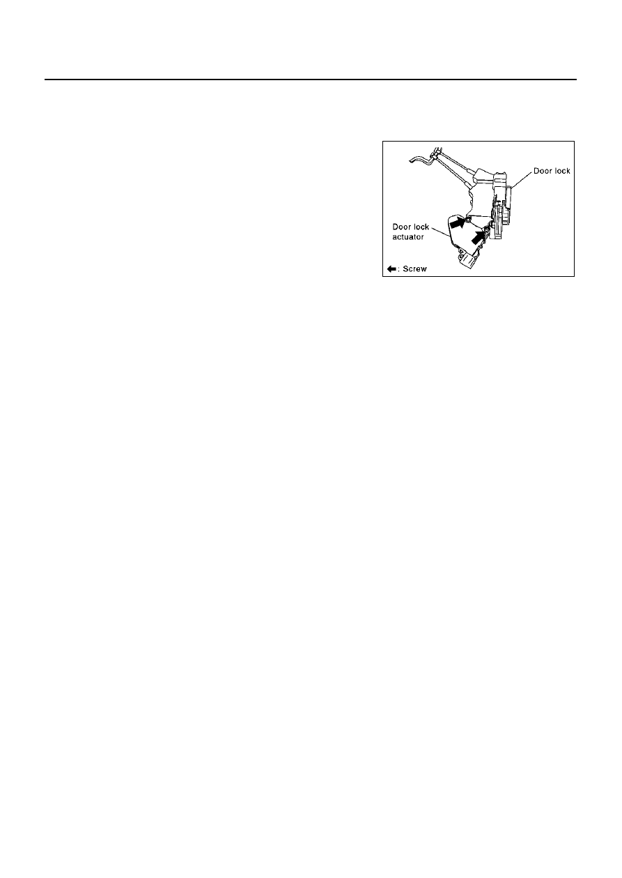
DISASSEMBLY
CAUTION:
Be sure to remove or install the actuator with the door lock assembly removed.
1.
Remove the mounting screws, and remove the actuator from the
door lock assembly.
2.
Pull the actuator straight downward to separate it from the door
lock assembly.
ASSEMBLY
1.
Align the actuator pivot with the cutout on the knob lever of the door lock assembly, then assemble the
actuator.
2.
Move the knob lever and the actuator pivot toward the lock-on direction, and check that it engages
securely.
PIIA3474E

REAR DOOR LOCK
BL-109
C
D
E
F
G
H
J
K
L
M
A
B
BL
REAR DOOR LOCK
PFP:82502
Components
EIS000HH
Inspection and Adjustment
EIS000HI
1.
Remove the rear door finisher. Refer to
EI-30, "Removal and Installation"
.
2.
Remove the frame assembly. Refer to
GW-54, "Removal and Installation"
EXTERIOR HANDLE ROD ADJUSTMENT
Rotate the bushing to adjust so that the clearance between the bush-
ing and rod becomes as shown in the figure.
CAUTION:
Be careful not to make the clearance 0 mm (0 in) or the rod
pressed continuously.
Removal and Installation of Door Lock
EIS000HJ
REMOVAL
1.
Remove the rear door finisher. Refer to
EI-30, "Removal and Installation"
2.
Remove the frame assembly. Refer to
GW-54, "Removal and Installation"
1.
Handle bracket
2.
Door lock assembly
3.
Door lock actuator
4.
Outside handle
5.
Lock knob cable
6.
Inside handle cable
7.
Inside handle
8.
Lock knob
PIIA3478E
SBT978

BL-110
REAR DOOR LOCK
3.
After gaining access to the interior handle on the back side of
the rear door finisher, disconnect the interior handle cable and
locking knob cable.
4.
Remove the mounting screws (TORX T30), remove the door
lock assembly.
5.
Disconnect the door lock actuator connector.
6.
Remove the exterior handle mounting bolts, and move the han-
dle backward to disengage it from the panel in front of the exte-
rior handle escutcheon, then remove the handle.
INSTALLATION
Install in the reverse order of removal.
CAUTION:
●
To install each rod, be sure to rotate the rod holder until a click is felt.
●
After installing, check operation.
●
After installing, perform fitting adjustment. Refer to
Disassembly and Assembly
EIS000HL
DISASSEMBLY
CAUTION:
Be sure to remove or install the actuator with the door lock assembly removed.
1.
Remove the mounting screws, and remove the actuator from the
door lock assembly.
2.
Pull the actuator straight downward to separate it from the door
lock assembly.
PIIA3476E
PIIA1090E
PIIA3479E
PIIA3480E
Нет комментариевНе стесняйтесь поделиться с нами вашим ценным мнением.
Текст