Infiniti FX35, FX50 (S51). Manual — part 544
AWD SYSTEM
DLN-11
< SYSTEM DESCRIPTION >
[TRANSFER: ETX13C]
C
E
F
G
H
I
J
K
L
M
A
B
DLN
N
O
P
4.
Main clutch transmits torque to front wheels according to pressing power.
• Transmission torque to front wheels is determined according
to command current.
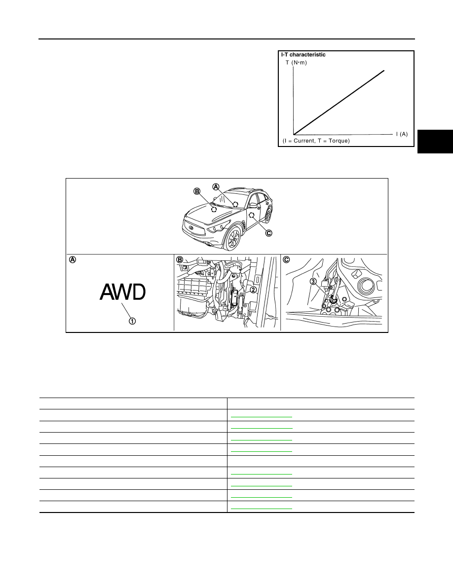
Component Parts Location
INFOID:0000000005249035
Component Description
INFOID:0000000005249036
SDIA1844E
1.
AWD warning lamp
2.
AWD control unit
3.
AWD solenoid harness connector
A.
Combination meter
B.
Glove box assembly removed
C.
Transfer assembly
JPDIE0126ZZ
Component parts
Reference/Function
AWD control unit
Wheel sensors
AWD solenoid
Transfer fluid temperature sensor
Electric controlled coupling
Transmits driving force to rear final drive.
AWD warning lamp
ABS actuator and electric unit (control unit)
ECM
Unified meter and A/C amp.

DLN-12
< SYSTEM DESCRIPTION >
[TRANSFER: ETX13C]
DIAGNOSIS SYSTEM (AWD CONTROL UNIT)
DIAGNOSIS SYSTEM (AWD CONTROL UNIT)
CONSULT-III Function (ALL MODE AWD/4WD)
INFOID:0000000005249037
FUNCTION
CONSULT-III can display each diagnostic item using the diagnostic test modes as follows.
ECU IDENTIFICATION
AWD control unit part number can be read.
SELF DIAGNOSTIC RESULT
Before performing the self-diagnosis, start the engine and drive vehicle at 30 km/h (19 MPH) or more for
approximately 1 minute.
Display Item List
.
How to Erase Self-Diagnostic Results
Before erasing DTC memory, start the engine and drive at 30 km/h (19 MPH) or more for approximately 1
minute. Check that ABS warning lamp turns OFF.
NOTE:
When AWD warning lamp is ON with system malfunction of DTC “C1203”, run the vehicle at 30 km/h (19MPH)
or more for a minute and check that ABS warning lamp is turned OFF. Then turn ignition switch OFF, and start
the engine again. Otherwise AWD warning lamp may not turned OFF even if it is normal.
DATA MONITOR
Display Item List
ACTIVE TEST
Description
Diagnostic test mode
Function
ECU Identification
AWD control unit part number can be read.
Self Diagnostic Result
Self-diagnostic results can be read and erased quickly.
Data Monitor
Input/Output data in the AWD control unit can be read.
Active Test
Diagnostic Test Mode in which CONSULT-III drives some actuators apart from the AWD control unit
and also shifts some parameters in a specified range.
Monitor item (Unit)
Remarks
STOP LAMP SW [On/Off]
Stop lamp switch signal status via CAN communication line is displayed.
ENG SPEED SIG [Run/Stop]
Engine status is displayed.
ETS ACTUATOR [On/Off]
Operating condition of AWD actuator relay (integrated in AWD control unit) is displayed.
4WD WARN LAMP [On/Off]
Control status of AWD warning lamp is displayed.
4WD MODE SW [##]
Mode switch is not equipped, but displayed.
4WD MODE MON [AUTO]
Control status of AWD is displayed.
DIS-TIRE MONI [mm]
Improper size tire installed condition is displayed.
P BRAKE SW [On/Off]
Parking brake switch signal status via CAN communication line is displayed.
BATTERY VOLT [V]
Power supply voltage for AWD control unit
THRTL POS SEN [%]
Throttle opening status is displayed.
ETS SOLENOID [A]
Monitored value of current at AWD solenoid
FR RH SENSOR [km/h] or [mph]
Wheel speed calculated by front RH wheel sensor signal is displayed.
FR LH SENSOR [km/h] or [mph]
Wheel speed calculated by front LH wheel sensor signal is displayed.
RR RH SENSOR [km/h] or [mph]
Wheel speed calculated by rear RH wheel sensor signal is displayed.
RR LH SENSOR [km/h] or [mph]
Wheel speed calculated by rear LH wheel sensor signal is displayed.

DIAGNOSIS SYSTEM (AWD CONTROL UNIT)
DLN-13
< SYSTEM DESCRIPTION >
[TRANSFER: ETX13C]
C
E
F
G
H
I
J
K
L
M
A
B
DLN
N
O
P
Use this mode to determine and identify the details of a malfunction based on self-diagnostic results or data
monitor. AWD control unit gives drive signal to actuator with receiving command from CONSULT-III to check
operation of actuator.
Test Item
CAUTION:
Never energize continuously for a long time.
Test item
Condition
Description
ETS S/V
(Detects AWD solenoid)
• Vehicle stopped
• Engine running
• No DTC detected
Change command current value to AWD solenoid, and then change driving
mode. (Monitor value is normal if it is within approx.
±
10% of command val-
ue.)
• Qu: Increase current value in increments of 0.2 A
• Qd: Decrease current value in increments of 0.2 A
• UP: Increase current value in increments of 0.02 A
• DOWN: Decrease current value in increments of 0.02 A

DLN-14
< DTC/CIRCUIT DIAGNOSIS >
[TRANSFER: ETX13C]
C1201 AWD CONTROL UNIT
DTC/CIRCUIT DIAGNOSIS
C1201 AWD CONTROL UNIT
Description
INFOID:0000000005249038
• Controls driving force distribution by signals from each sensor from rear wheel driving mode (0:100) to 4-
wheel driving mode (50:50).
• Rear wheel driving conditions is available by fail-safe function if malfunction is detected in AWD system.
DTC Logic
INFOID:0000000005249039
DTC DETECTION LOGIC
DTC CONFIRMATION PROCEDURE
1.
DTC REPRODUCTION PROCEDURE
With CONSULT-III
1.
Turn the ignition switch OFF to ON.
2.
Perform self-diagnosis for “ALL MODE AWD/4WD”.
Is DTC “C1201” detected?
YES
>> Proceed to diagnosis procedure. Refer to
NO
>> INSPECTION END
Diagnosis Procedure
INFOID:0000000005249040
1.
PERFORM SELF-DIAGNOSIS
With CONSULT-III
1.
Erase self-diagnostic results for “ALL MODE AWD/4WD”.
2.
Turn the ignition switch OFF, and then wait 10 seconds or more.
3.
Perform self-diagnosis for “ALL MODE AWD/4WD”.
Is DTC “C1201” detected?
YES
>> Replace AWD control unit. Refer to
NO
>> Check AWD control unit pin terminals for damage or loose connection with harness connector. If
any items are damaged, repair or replace error-detected parts.
DTC
Display item
Malfunction detected condition
Possible cause
C1201
CONTROLLER FAILURE
Malfunction has occurred inside AWD
control unit.
Internal malfunction of AWD control unit
Нет комментариевНе стесняйтесь поделиться с нами вашим ценным мнением.
Текст