Infiniti FX35, FX50 (S51). Manual — part 490
REMOTE KEYLESS ENTRY RECEIVER
DLK-83
< DTC/CIRCUIT DIAGNOSIS >
C
D
E
F
G
H
I
J
L
M
A
B
DLK
N
O
P
REMOTE KEYLESS ENTRY RECEIVER
Description
INFOID:0000000005239570
Receives Intelligent Key operation and transmits to BCM.
Component Function Check
INFOID:0000000005239571
1.
CHECK FUNCTION
With CONSULT-III
Check remote keyless entry receiver (“RKE OPE COUN1”) in Data Monitor mode using CONSULT-III.
Is the inspection result normal?
YES
>> Remote keyless entry receiver is OK.
NO
>> Refer to
.
Diagnosis Procedure
INFOID:0000000005239572
1.
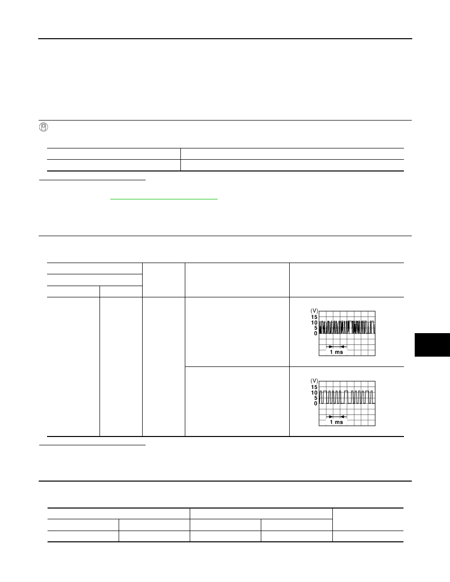
CHECK REMOTE KEYLESS ENTRY RECEIVER OUTPUT SIGNAL
1.
Turn ignition switch OFF.
2.
Check signal between remote keyless entry receiver harness connector and ground using oscilloscope.
Is the inspection result normal?
YES
>> GO TO 3.
NO
>> GO TO 2.
2.
CHECK REMOTE KEYLESS ENTRY RECEIVER CIRCUIT 1
1.
Disconnect BCM connector and remote keyless entry receiver connector
2.
Check continuity between BCM harness connector and remote keyless entry receiver harness connector.
3.
Check continuity between BCM harness connector and ground.
Monitor item
Condition
RKE OPE COUN1
Checks whether value changes when operating Intelligent Key.
(+)
(–)
Condition
Signal
(Reference value)
Remote keyless entry receiver
Connector
Terminal
M104
2
Ground
Waiting
(All door closed)
When signal is received
(All door closed)
JMKIA0064GB
JMKIA0065GB
BCM
Remote keyless entry receiver
Continuity
Connector
Terminal
Connector
Terminal
M122
83
M104
2
Existed

DLK-84
< DTC/CIRCUIT DIAGNOSIS >
REMOTE KEYLESS ENTRY RECEIVER
Is the inspection result normal?
YES
>> Replace BCM. Refer to
BCS-83, "Removal and Installation"
NO
>> Repair or replace harness.
3.
CHECK REMOTE KEYLESS ENTRY RECEIVER POWER SUPPLY
1.
Disconnect remote keyless entry receiver.
2.
Check voltage between remote keyless entry receiver harness connector and ground.
Is the inspection result normal?
YES
>> GO TO 5.
NO
>> GO TO 4.
4.
CHECK REMOTE KEYLESS ENTRY RECEIVER CIRCUIT 2
1.
Disconnect BCM connector.
2.
Check continuity between BCM harness connector and remote keyless entry receiver harness connector.
3.
Check continuity between BCM harness connector and ground.
Is the inspection result normal?
YES
>> Replace BCM. Refer to
BCS-83, "Removal and Installation"
NO
>> Repair or replace harness.
5.
CHECK REMOTE KEYLESS ENTRY RECEIVER GROUND CIRCUIT
Check continuity between remote keyless entry receiver harness connector and ground.
Is the inspection result normal?
YES
>> Replace remote keyless entry receiver. Refer to
DLK-287, "Removal and Installation"
NO
>> GO TO 6.
6.
CHECK REMOTE KEYLESS ENTRY RECEIVER CIRCUIT 3
1.
Disconnect BCM connector.
2.
Check continuity between BCM harness connector and remote keyless entry receiver harness connector.
BCM
Ground
Continuity
Connector
Terminal
M122
83
Not existed
(+)
(–)
Voltage (V)
(Approx.)
Remote keyless entry receiver
Connector
Terminal
M104
4
Ground
Battery voltage
BCM
Remote keyless entry receiver
Continuity
Connector
Terminal
Connector
Terminal
M122
103
M104
4
Existed
BCM
Ground
Continuity
Connector
Terminal
M122
103
Not existed
Remote keyless entry receiver
Ground
Continuity
Connector
Terminal
M104
1
Existed
BCM
Remote keyless entry receiver
Continuity
Connector
Terminal
Connector
Terminal
M123
137
M104
1
Existed
REMOTE KEYLESS ENTRY RECEIVER
DLK-85
< DTC/CIRCUIT DIAGNOSIS >
C
D
E
F
G
H
I
J
L
M
A
B
DLK
N
O
P
Is the inspection result normal?
YES
>> Replace BCM. Refer to
BCS-83, "Removal and Installation"
NO
>> Repair or replace harness.
DLK-86
< DTC/CIRCUIT DIAGNOSIS >
BACK DOOR OPENER SWITCH
BACK DOOR OPENER SWITCH
Description
INFOID:0000000005239573
Output back door open signal to BCM.
Component Function Check
INFOID:0000000005239574
1.
CHECK FUNCTION
Check back door opener switch (“TR/BD OPEN SW”) in “Data Monitor mode using CONSULT-III.
• When back door opener switch is turned to “ON”.
Is the inspection result normal?
YES
>> Back door opener switch is OK.
NO
>> Refer to
.
Diagnosis Procedure
INFOID:0000000005239575
1.
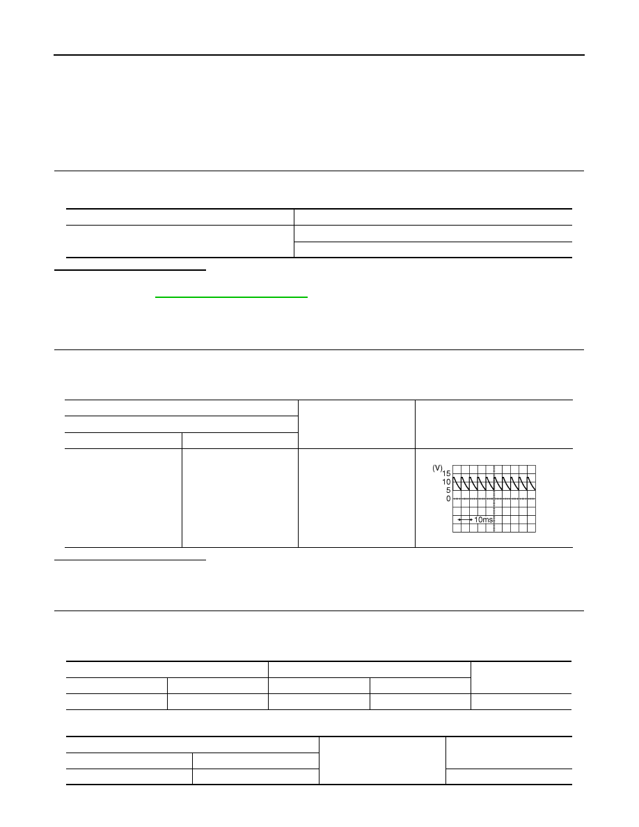
CHECK BACK DOOR OPEN INPUT SIGNAL
1.
Turn ignition switch OFF.
2.
Disconnect back door opener switch connector.
3.
Check signal between back door opener switch harness connector and ground.
Is the inspection result normal?
YES
>> GO TO 3.
NO
>> GO TO 2.
2.
CHECK BACK DOOR OPENER SWITCH CIRCUIT
1.
Disconnect BCM connector.
2.
Check continuity between BCM harness connector and back door opener switch assembly harness con-
nector.
3.
Check continuity between BCM harness connector and ground.
Monitor item
Condition
TR/BD OPEN SW
Back door opener switch is pressed: ON
Back door opener switch is released: OFF
(+)
(–)
Signal
(Reference value)
Back door opener switch
Connector
Terminal
D114
1
Ground
JPMIA0594GB
BCM
Back door opener switch
Continuity
Connector
Terminal
Connector
Terminal
M121
67
D114
1
Existed
BCM
Ground
Continuity
Connector
Terminal
M121
67
Not existed
Нет комментариевНе стесняйтесь поделиться с нами вашим ценным мнением.
Текст