Infiniti FX35, FX50 (S51). Manual — part 1814
DIAGNOSIS SYSTEM (TCM)
TM-63
< SYSTEM DESCRIPTION >
[7AT: RE7R01A (VQ35HR)]
C
E
F
G
H
I
J
K
L
M
A
B
TM
N
O
P
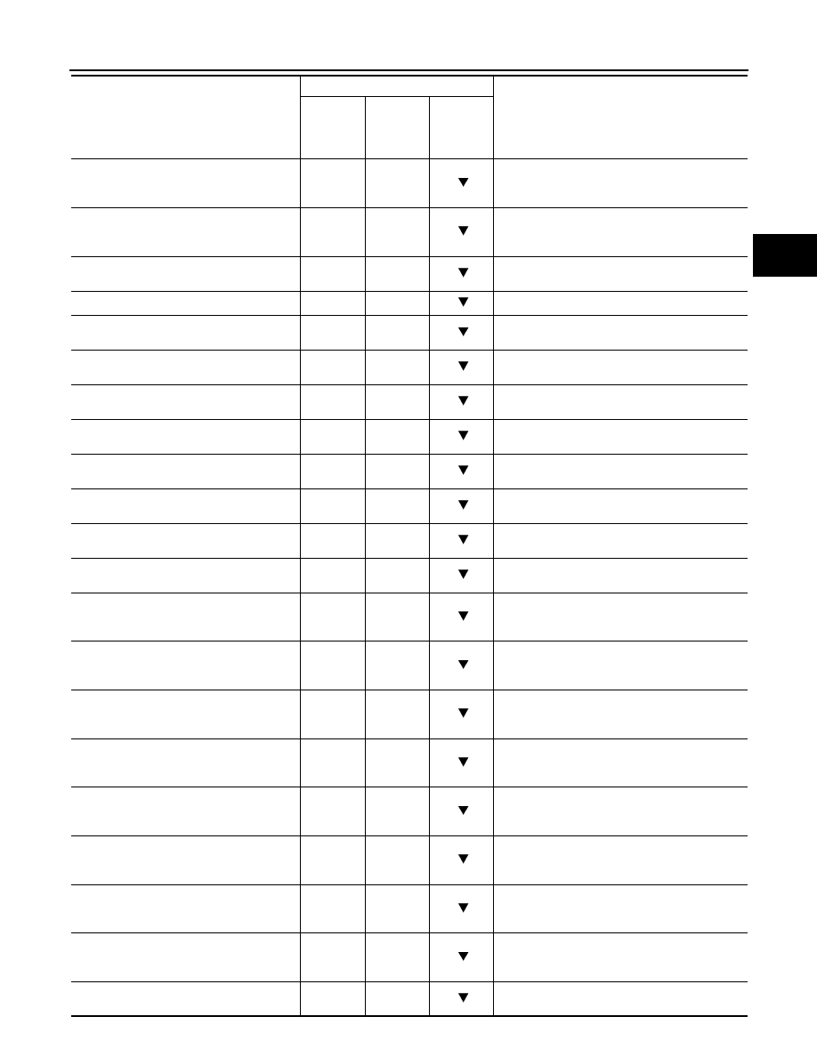
ATF TEMP 1
(
°
C or
°
F)
X
X
Displays the ATF temperature of oil pan calculat-
ed from the signal voltage of A/T fluid tempera-
ture sensor.
ATF TEMP 2
(
°
C or
°
F)
X
X
Displays the ATF temperature estimated value of
torque converter outlet calculated from the signal
voltage of A/T fluid temperature sensor.
ATF TEMP SE 1
(V)
—
—
Displays the signal voltage of A/T fluid tempera-
ture sensor.
BATTERY VOLT
(V)
X
—
Displays the power supply voltage of TCM.
LINE PRES SOL
(A)
—
X
Displays the command current from TCM to the
line pressure solenoid.
TCC SOLENOID
(A)
—
X
Displays the command current from TCM to the
torque converter clutch solenoid.
L/B SOLENOID
(A)
—
X
Displays the command current from TCM to the
low brake solenoid.
FR/B SOLENOID
(A)
—
X
Displays the command current from TCM to the
front brake solenoid.
HLR/C SOL
(A)
—
X
Displays the command current from TCM to the
high and low reverse clutch solenoid.
I/C SOLENOID
(A)
—
X
Displays the command current from TCM to the
input clutch solenoid.
D/C SOLENOID
(A)
—
X
Displays the command current from TCM to the
direct clutch solenoid.
2346/B SOL
(A)
—
X
Displays the command current from TCM to the
2346 brake solenoid.
L/P SOL MON
(A)
—
—
Monitors the command current from TCM to the
line pressure solenoid, and displays the monitor
value.
TCC SOL MON
(A)
—
—
Monitors the command current from TCM to the
torque converter clutch solenoid, and displays
the monitor value.
L/B SOL MON
(A)
—
—
Monitors the command current from TCM to the
low brake solenoid, and displays the monitor val-
ue.
FR/B SOL MON
(A)
—
—
Monitors the command current from TCM to the
front brake solenoid, and displays the monitor
value.
HLR/C SOL MON
(A)
—
—
Monitors the command current from TCM to the
high and low reverse clutch solenoid, and dis-
plays the monitor value.
I/C SOL MON
(A)
—
—
Monitors the command current from TCM to the
input clutch solenoid, and displays the monitor
value.
D/C SOL MON
(A)
—
—
Monitors the command current from TCM to the
direct clutch solenoid, and displays the monitor
value.
2346/B SOL MON
(A)
—
—
Monitors the command current from TCM to the
2346 brake solenoid, and displays the monitor
value.
GEAR RATIO
—
X
Displays the gear ratio calculated from input rev-
olution and output revolution.
Monitored item (Unit)
Monitor Item Selection
Remarks
ECU IN-
PUT SIG-
NALS
MAIN
SIGNALS
SELEC-
TION
FROM
ITEM
TM-64
< SYSTEM DESCRIPTION >
[7AT: RE7R01A (VQ35HR)]
DIAGNOSIS SYSTEM (TCM)
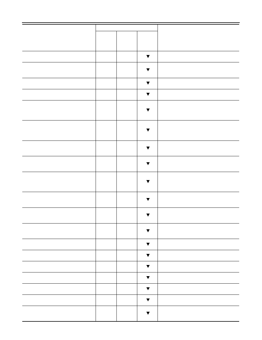
ENGINE TORQUE
(Nm)
—
—
Displays the engine torque estimated value re-
ceived via CAN communication.
ENG TORQUE D
(Nm)
—
—
Displays the engine torque estimated value re-
flected the requested torque of each control unit
received via CAN communication.
INPUT TRQ S
(Nm)
—
—
Displays the input torque using for the oil pres-
sure calculation process of shift change control.
INPUT TRQ L/P
(Nm)
—
—
Displays the input torque using for the oil pres-
sure calculation process of line pressure control.
TRGT PRES L/P
(kPa, kg/cm
2
or psi)
—
—
Displays the target oil pressure value of torque
converter clutch solenoid valve calculated by the
oil pressure calculation process of lock-up con-
trol.
TRGT PRES TCC
(kPa, kg/cm
2
or psi)
—
—
Displays the target oil pressure value of torque
converter clutch solenoid valve calculated by the
oil pressure calculation process of shift change
control.
TRGT PRES L/B
(kPa, kg/cm
2
or psi)
—
—
Displays the target oil pressure value of low
brake solenoid valve calculated by the oil pres-
sure calculation process of shift change control.
TRGT PRE FR/B
(kPa, kg/cm
2
or psi)
—
—
Displays the target oil pressure value of front
brake solenoid valve calculated by the oil pres-
sure calculation process of shift change control.
TRG PRE HLR/C
(kPa, kg/cm
2
or psi)
—
—
Displays the target oil pressure value of high and
low reverse clutch solenoid valve calculated by
the oil pressure calculation process of shift
change control.
TRGT PRES I/C
(kPa, kg/cm
2
or psi)
—
—
Displays the target oil pressure value of input
clutch solenoid valve calculated by the oil pres-
sure calculation process of shift change control.
TRGT PRES D/C
(kPa, kg/cm
2
or psi)
—
—
Displays the target oil pressure value of direct
clutch solenoid valve calculated by the oil pres-
sure calculation process of shift change control.
TRG PRE 2346/B
(kPa, kg/cm
2
or psi)
—
—
Displays the target oil pressure value of 2346
brake solenoid valve calculated by the oil pres-
sure calculation process of shift change control.
SHIFT PATTERN
—
—
Displays the gear change data using the shift pat-
tern control.
VEHICLE SPEED
(km/h or mph)
—
—
Displays the vehicle speed for control using the
control of TCM.
RANGE SW 4
(ON/OFF)
X
—
Displays the operation status of transmission
range switch 4.
RANGE SW 3
(ON/OFF)
X
—
Displays the operation status of transmission
range switch 3.
RANGE SW 2
(ON/OFF)
X
—
Displays the operation status of transmission
range switch 2.
RANGE SW 1
(ON/OFF)
X
—
Displays the operation status of transmission
range switch 1.
SFT DWN ST SW
(ON/OFF)
X
—
• Displays the operation status of paddle shifter
(down switch).
• Not mounted but displayed.
Monitored item (Unit)
Monitor Item Selection
Remarks
ECU IN-
PUT SIG-
NALS
MAIN
SIGNALS
SELEC-
TION
FROM
ITEM
DIAGNOSIS SYSTEM (TCM)
TM-65
< SYSTEM DESCRIPTION >
[7AT: RE7R01A (VQ35HR)]
C
E
F
G
H
I
J
K
L
M
A
B
TM
N
O
P
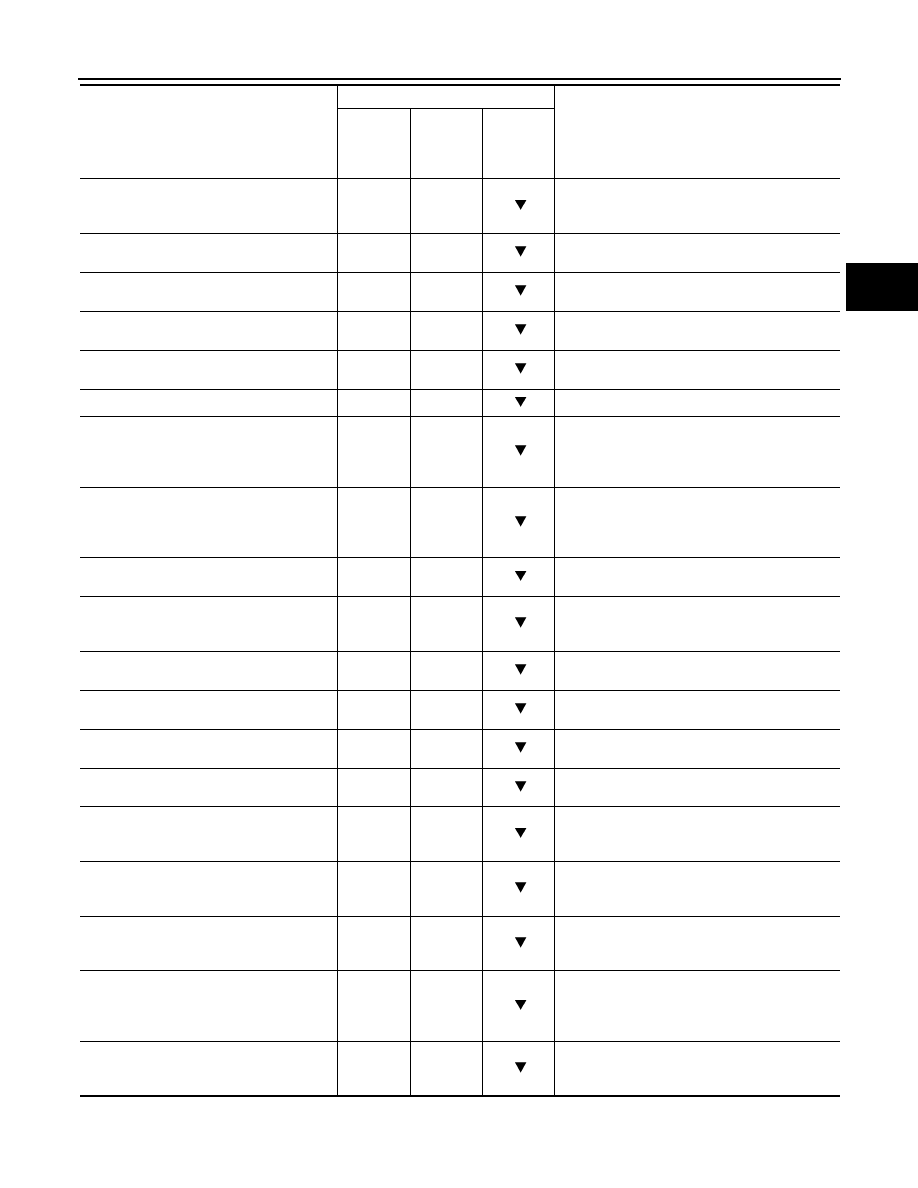
SFT UP ST SW
(ON/OFF)
X
—
• Displays the operation status of paddle shifter
(up switch).
• Not mounted but displayed.
DOWN SW LEVER
(ON/OFF)
X
—
Displays the operation status of selector lever
(down switch).
UP SW LEVER
(ON/OFF)
X
—
Displays the operation status of selector lever (up
switch).
NON M-MODE SW
(ON/OFF)
X
—
Displays whether the selector lever is in any po-
sition other than manual shift gate position.
MANU MODE SW
(ON/OFF)
X
—
Displays whether the selector lever is in the man-
ual shift gate position.
DS RANGE
(ON/OFF)
—
—
Displays whether it is the DS mode.
1 POSITION SW
(ON/OFF)
X
—
• Displays the reception status of 1 position
switch signal received via CAN communica-
tion.
• Not mounted but displayed.
OD CONT SW
(ON/OFF)
X
—
• Displays the reception status of overdrive con-
trol switch signal received via CAN communi-
cation.
• Not mounted but displayed.
BRAKESW
(ON/OFF)
X
—
Displays the reception status of stop lamp switch
signal received via CAN communication.
POWERSHIFT SW
(ON/OFF)
X
—
• Displays the reception status of POWER mode
signal received via CAN communication.
• Not mounted but displayed.
ASCD-OD CUT
(ON/OFF)
X
—
Displays the reception status of ASCD OD cancel
request signal received via CAN communication.
ASCD-CRUISE
(ON/OFF)
X
—
Displays the reception status of ASCD operation
signal received via CAN communication.
ABS SIGNAL
(ON/OFF)
X
—
Displays the reception status of ABS operation
signal received via CAN communication.
TCS GR/P KEEP
(ON/OFF)
X
—
Displays the reception status of TCS gear keep
request signal received via CAN communication.
TCS SIGNAL 2
(ON/OFF)
X
—
Displays whether the reception value of A/T shift
schedule change demand signal received via
CAN communication is “cold”.
TCS SIGNAL 1
(ON/OFF)
X
—
Displays whether the reception value of A/T shift
schedule change demand signal received via
CAN communication is “warm”.
LOW/B PARTS
(FAIL/NOTFAIL)
—
—
In “Final fail-safe” mode, displays whether the
identified malfunction point judged by TCM is the
related parts of low brake.
HC/IC/FRB PARTS
(FAIL/NOTFAIL)
—
—
In “Final fail-safe” mode, displays whether the
identified malfunction point judged by TCM is the
related parts of high and low reversed clutch, in-
put clutch or front brake.
IC/FRB PARTS
(FAIL/NOTFAIL)
—
—
In “Final fail-safe” mode, displays whether the
identified malfunction point judged by TCM is the
related parts of input clutch or front brake.
Monitored item (Unit)
Monitor Item Selection
Remarks
ECU IN-
PUT SIG-
NALS
MAIN
SIGNALS
SELEC-
TION
FROM
ITEM
TM-66
< SYSTEM DESCRIPTION >
[7AT: RE7R01A (VQ35HR)]
DIAGNOSIS SYSTEM (TCM)
DTC & SRT CONFIRMATION
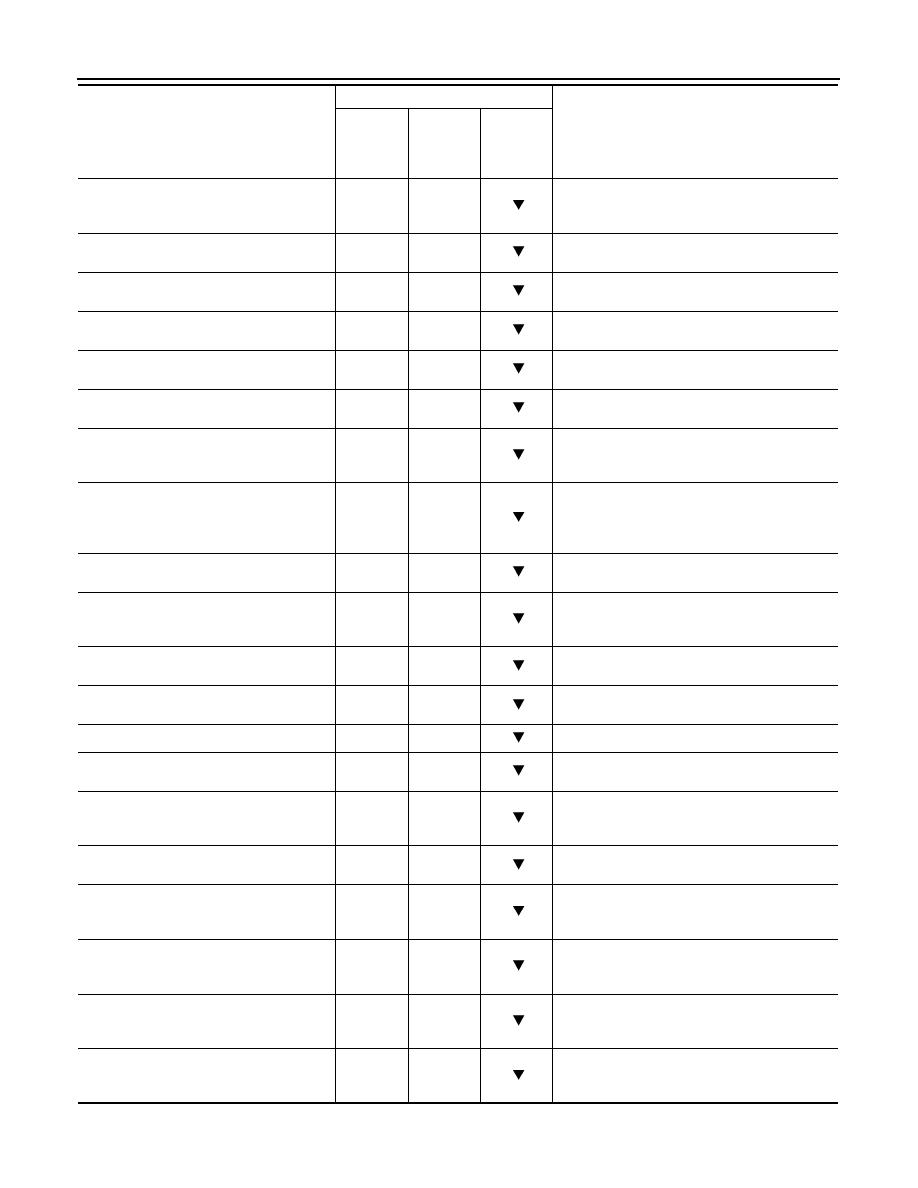
HLR/C PARTS
(FAIL/NOTFAIL)
—
—
In “Final fail-safe” mode, displays whether the
identified malfunction point judged by TCM is the
related parts of high and low reversed clutch.
W/O THL POS
(ON/OFF)
X
—
Displays the kickdown condition signal status re-
ceived via CAN communication.
CLSD THL POS
(ON/OFF)
X
—
Displays the idling status signal status received
via CAN communication.
DRV CST JUDGE
(DRIVE/COAST)
—
—
Displays the judgment results of “driving” or
“coasting” judged by TCM.
SHIFT IND SIGNAL
—
—
Displays the transmission value of shift position
signal transmitted via CAN communication.
STARTER RELAY
(ON/OFF)
—
—
Displays the command status from TCM to start-
er relay.
F-SAFE IND/L
(ON/OFF)
—
—
Displays the transmission status of A/T CHECK
indicator lamp signal transmitted via CAN com-
munication.
ATF WARN LAMP
(ON/OFF)
—
—
• Displays the transmission status of ATF tem-
perature signal transmitted via CAN communi-
cation.
• Not mounted but displayed.
MANU MODE IND
(ON/OFF)
—
—
Displays the transmission status of manual mode
signal transmitted via CAN communication.
ON OFF SOL MON
(ON/OFF)
—
—
Monitors the command value from TCM to the
anti-interlock solenoid, and displays the monitor
status.
START RLY MON
(ON/OFF)
—
—
Monitors the command value from TCM to the
starter relay, and displays the monitor status.
ON OFF SOL
(ON/OFF)
—
—
Displays the command status from TCM to anti-
interlock solenoid.
SLCT LVR POSI
—
X
Displays the shift positions recognized by TCM.
GEAR
—
X
Displays the current transmission gear position
recognized by TCM.
NEXT GR POSI
—
—
Displays the target gear position of gear change
that is calculated based on the vehicle speed in-
formation and throttle information.
SHIFT MODE
—
—
Displays the transmission driving mode recog-
nized by TCM.
D/C PARTS
(FAIL/NOTFAIL)
—
—
In “Final fail-safe” mode, displays whether the
identified malfunction point judged by TCM is the
related parts of direct clutch.
FR/B PARTS
(FAIL/NOTFAIL)
—
—
In “Final fail-safe” mode, displays whether the
identified malfunction point judged by TCM is the
related parts of front brake.
2346/B PARTS
(FAIL/NOTFAIL)
—
—
In “Final fail-safe” mode, displays whether the
identified malfunction point judged by TCM is the
related parts of 2346 brake.
2346B/DC PARTS
(FAIL/NOTFAIL)
—
—
In “Final fail-safe” mode, displays whether the
identified malfunction point judged by TCM is the
related parts of 2346 brake or direct clutch.
Monitored item (Unit)
Monitor Item Selection
Remarks
ECU IN-
PUT SIG-
NALS
MAIN
SIGNALS
SELEC-
TION
FROM
ITEM
Нет комментариевНе стесняйтесь поделиться с нами вашим ценным мнением.
Текст