Infiniti FX35, FX50 (S51). Manual — part 818

P0132, P0152 A/F SENSOR 1
EC-813
< DTC/CIRCUIT DIAGNOSIS >
[VK50VE]
C
D
E
F
G
H
I
J
K
L
M
A
EC
N
P
O
With GST
Follow the procedure “With CONSULT-III” above.
Is the indication constantly approx. 5 V?
YES
>> Go to
NO
>> GO TO 3.
3.
PERFORM DTC CONFIRMATION PROCEDURE
With CONSULT-III
1.
Turn ignition switch OFF and wait at least 10 seconds.
2.
Turn ignition switch ON.
3.
Turn ignition switch OFF and wait at least 10 seconds.
4.
Restart engine.
5.
Drive and accelerate vehicle to more than 40 km/h (25 MPH) within 20 seconds after restarting engine.
CAUTION:
Always drive vehicle at a safe speed.
6.
Maintain the following conditions for approximately 20 consecutive seconds.
NOTE:
• Keep the accelerator pedal as steady as possible during cruising.
• If this procedure is not completed within 1 minute after restarting engine at step 1, return to step
1.
7.
Check 1st trip DTC.
With GST
Follow the procedure “With CONSULT-III” above.
Is 1st trip DTC detected?
YES
>> Go to
NO
>> INSPECTION END
Diagnosis Procedure
INFOID:0000000005237300
1.
CHECK GROUND CONNECTION
1.
Turn ignition switch OFF.
2.
Check ground connection M95. Refer to Ground Inspection in
Is the inspection result normal?
YES
>> GO TO 2.
NO
>> Repair or replace ground connection.
2.
CHECK AIR FUEL RATIO SENSOR 1 POWER SUPPLY CIRCUIT
1.
Disconnect air fuel ratio (A/F) sensor 1 harness connector.
2.
Turn ignition switch ON.
3.
Check the voltage between A/F sensor 1 harness connector and ground.
Is the inspection result normal?
YES
>> GO TO 4.
NO
>> GO TO 3.
3.
DETECT MALFUNCTIONING PART
ENG SPEED
1,000 - 3,200 rpm
VHCL SPEED SE
More than 40 km/h (25 mph)
B/FUEL SCHDL
1.5 - 9.0 msec
Selector lever
Suitable position
DTC
A/F sensor 1
Ground
Voltage
Bank
Connector
Terminal
P0132
1
F67
4
Ground
Battery voltage
P0152
2
F68
4

EC-814
< DTC/CIRCUIT DIAGNOSIS >
[VK50VE]
P0132, P0152 A/F SENSOR 1
Check the following.
• Harness connectors E10, F10
• IPDM E/R harness connector E7
• 15 A fuse (No. 46)
• Harness for open or short between A/F sensor 1 and fuse
>> Repair or replace harness or connectors.
4.
CHECK A/F SENSOR 1 INPUT SIGNAL CIRCUIT FOR OPEN AND SHORT
1.
Turn ignition switch OFF.
2.
Disconnect ECM harness connector.
3.
Check the continuity between A/F sensor 1 harness connector and ECM harness connector.
4.
Check the continuity between A/F sensor 1 harness connector and ground, or ECM harness connector
and ground.
5.
Also check harness for short to power.
Is the inspection result normal?
YES
>> GO TO 5.
NO
>> Repair open circuit, short to ground or short to power in harness or connectors.
5.
CHECK INTERMITTENT INCIDENT
Perform
GI-36, "Intermittent Incident"
.
Is the inspection result normal?
YES
>> GO TO 6.
NO
>> Repair or replace malfunctioning part.
6.
REPLACE A/F SENSOR 1
Replace malfunctioning A/F sensor 1.
CAUTION:
• Discard any A/F sensor which has been dropped from a height of more than 0.5 m (19.7 in) onto a
hard surface such as a concrete floor; use a new one.
• Before installing new A/F sensor, clean exhaust system threads using Oxygen Sensor Thread
Cleaner [commercial service tool (J-43897-18 or J-43897-12)] and approved anti-seize lubricant
(commercial service tool).
>> INSPECTION END
DTC
A/F sensor 1
ECM
Continuity
Bank
Connector
Terminal
Connector
Terminal
P0132
1
F67
1
F111
81
Existed
2
82
P0152
2
F68
1
85
2
86
DTC
A/F sensor 1
ECM
Ground
Continuity
Bank
Connector
Terminal
Connector
Terminal
P0132
1
F67
1
F111
81
Ground
Not existed
2
82
P0152
2
F68
1
85
2
86
P0133, P0153 A/F SENSOR 1
EC-815
< DTC/CIRCUIT DIAGNOSIS >
[VK50VE]
C
D
E
F
G
H
I
J
K
L
M
A
EC
N
P
O
P0133, P0153 A/F SENSOR 1
Description
INFOID:0000000005237301
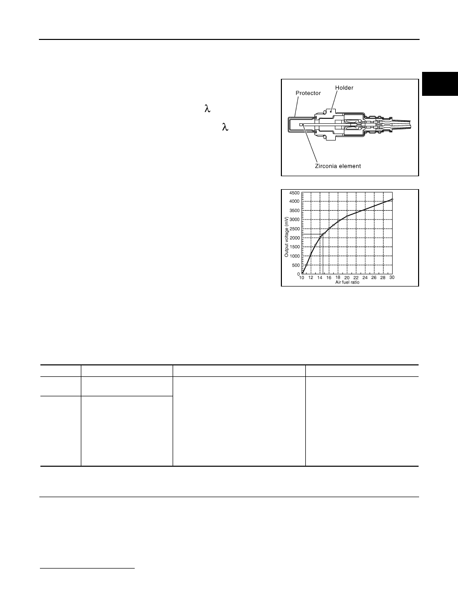
The air fuel ratio (A/F) sensor 1 is a planar one-cell limit current sen-
sor. The sensor element of the A/F sensor 1 is composed an elec-
trode layer, which transports ions. It has a heater in the element.
The sensor is capable of precise measurement = 1, but also in the
lean and rich range. Together with its control electronics, the sensor
outputs a clear, continuous signal throughout a wide range.
The exhaust gas components diffuse through the diffusion layer at
the sensor cell. An electrode layer is applied voltage, and this current
relative oxygen density in lean. Also this current relative hydrocar-
bon density in rich.
Therefore, the A/F sensor 1 is able to indicate air fuel ratio by this
electrode layer of current. In addition, a heater is integrated in the
sensor to ensure the required operating temperature of approxi-
mately 800
°
C (1,472
°
F).
DTC Logic
INFOID:0000000005237302
DTC DETECTION LOGIC
To judge the malfunction of A/F sensor 1, this diagnosis measures response time of the A/F signal computed
by ECM from the A/F sensor 1 signal. The time is compensated by engine operating (speed and load), fuel
feedback control constant, and the A/F sensor 1 temperature index. Judgment is based on whether the com-
pensated time (the A/F signal cycling time index) is inordinately long or not.
DTC CONFIRMATION PROCEDURE
1.
PRECONDITIONING
If DTC Confirmation Procedure has been previously conducted, always perform the following procedure
before conducting the next test.
1.
Turn ignition switch OFF and wait at least 10 seconds.
2.
Turn ignition switch ON.
3.
Turn ignition switch OFF and wait at least 10 seconds.
TESTING CONDITION:
Before performing the following procedure, confirm that battery voltage is more than 11 V at idle.
Will CONSULT-III be used?
JMBIA0112GB
PBIB3354E
DTC No.
Trouble diagnosis name
DTC detecting condition
Possible Cause
P0133
Air fuel ratio (A/F) sensor 1
(bank 1) circuit slow response
• The response of the A/F signal computed
by ECM from A/F sensor 1 signal takes
more than the specified time.
• Harness or connectors
(The A/F sensor 1 circuit is open or
shorted.)
• A/F sensor 1
• A/F sensor 1 heater
• Fuel pressure
• Fuel injector
• Intake air leaks
• Exhaust gas leaks
• PCV
• Mass air flow sensor
P0153
Air fuel ratio (A/F) sensor 1
(bank 2) circuit slow response

EC-816
< DTC/CIRCUIT DIAGNOSIS >
[VK50VE]
P0133, P0153 A/F SENSOR 1
YES
>> GO TO 2.
NO
>> GO TO 5.
2.
PERFORM DTC CONFIRMATION PROCEDURE-I
With CONSULT-III
1.
Start engine and warm it up to normal operating temperature.
2.
Turn ignition switch OFF and wait at least 10 seconds.
3.
Turn ignition switch ON.
4.
Turn ignition switch OFF and wait at least 10 seconds.
5.
Restart engine and keep the engine speed between 3,500 and 4,000 rpm for at least 1 minute under no
load.
6.
Let engine idle for 1 minute.
7.
Select “A/F SEN1(B1) P1278/P1279” (for DTC P0133) or “A/F SEN1(B2) P1288/P1289” (for DTC P0153)
of “A/F SEN1” in “DTC WORK SUPPORT” mode with CONSULT-III.
8.
Touch “START”.
Is “COMPLETED” displayed on CONSULT-III screen?
YES
>> GO TO 3
NO
>> GO TO 4.
3.
PERFORM DTC CONFIRMATION PROCEDURE-II
Touch “SELF-DIAG RESULT”.
Which is displayed on CONSULT-III screen?
OK
>> INSPECTION END
NG
>> Go to
4.
PERFORM DTC CONFIRMATION PROCEDURE-II
1.
After perform the following procedure, “TESTING” will be displayed on the CONSULT-III screen.
-
Increase the engine speed up to between 4,000 and 5,000 rpm and maintain that speed for 10 seconds.
-
Fully release accelerator pedal and then let engine idle for approximately 10 seconds.
If “TESTING” is not displayed after 10 seconds, refer to
EC-728, "Component Function Check"
2.
Wait for approximately 20 seconds at idle under the condition that “TESTING” is displayed on the CON-
SULT-III screen.
3.
Check that “TESTING” changes to “COMPLETED”.
If “TESTING” changed to “OUT OF CONDITION”, refer to
EC-728, "Component Function Check"
.
4.
Touch “SELF-DIAG RESULT”.
Which is displayed on CONSULT-III screen?
OK
>> INSPECTION END
NG
>> Go to
5.
CHECK AIR-FUEL RATIO SELF-LEARNING VALUE
With GST
1.
Start engine and warm it up to normal operating temperature.
2.
Select Service $01 with GST.
3.
Calculate the total value of “Short term fuel trim” and “Long term fuel trim” indications.
Is the total percentage within
±
15%?
YES
>> GO TO 7.
NO
>> GO TO 6.
6.
DETECT MALFUNCTIONING PART
Check the following.
• Intake air leaks
• Exhaust gas leaks
• Incorrect fuel pressure
• Lack of fuel
• Fuel injector
• Incorrect PCV hose connection
• PCV valve
• Mass air flow sensor
Нет комментариевНе стесняйтесь поделиться с нами вашим ценным мнением.
Текст