Infiniti FX35, FX50 (S51). Manual — part 1840
A/T POSITION
TM-167
< PERIODIC MAINTENANCE >
[7AT: RE7R01A (VQ35HR)]
C
E
F
G
H
I
J
K
L
M
A
B
TM
N
O
P
A/T POSITION
Inspection and Adjustment
INFOID:0000000005250150
INSPECTION
1.
Place selector lever in “P” position, and turn ignition switch ON (engine stop).
2.
Check that selector lever can be shifted to other than “P” position when brake pedal is depressed. Also
check that selector lever can be shifted from “P” position only when brake pedal is depressed.
3.
Shift the selector lever and check for excessive effort, sticking, noise or rattle.
4.
Confirm that the selector lever stops at each position by feeling the engagement when it is moved through
all the positions. Check whether or not the actual position the selector lever matches the position shown
by the shift position indicator and the A/T body.
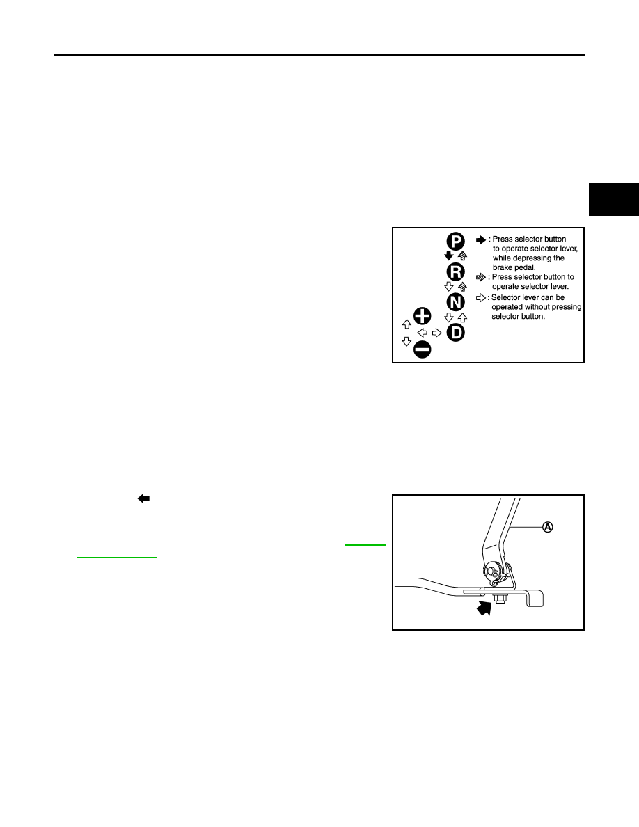
5.
The method of operating the lever to individual positions cor-
rectly is shown in the figure.
6.
When selector button is pressed in “P”, “R”, or “N” position with-
out applying forward/backward force to selector lever, check but-
ton operation for sticking.
7.
Confirm that the back-up lamps illuminate only when lever is
placed in the “R” position. Confirm that the back-up lamps do not
illuminate when selector lever is pushed against “R” position in
the “P” or “N” position.
8.
Confirm that the engine can only be started with the selector
lever in the “P” and “N” positions. (With selector lever in the “P”
position, engine can be started even when selector lever is
moved forward and backward.)
9.
Make sure that A/T is locked completely in “P” position.
10. DS mode must be indicated on the combination meter when the selector lever is shifted to the manual
shift gate. When the selector lever is shifted to the “+” or “
−
” side in the DS mode, manual mode should be
indicated on the combination meter.
In addition, a set shift position must be changed when the selector lever is shifted to the “+” or “
−
” side in
the manual mode. (Only while driving.)
ADJUSTMENT
1.
Loosen nut (
).
2.
Place manual lever and selector lever in “P” position.
3.
While pressing lower lever (A) toward rear of vehicle (in “P” posi-
tion direction), tighten nut to specified torque. Refer to
CAUTION:
Be careful not to touch the control rod while pressing lower
lever of A/T shift selector assembly.
NOTE:
Press lower lever of A/T shift selector assembly with a force of
approximately 1 kg (9.8 N).
JSDIA0790GB
JPDIA0885ZZ
TM-168
< REMOVAL AND INSTALLATION >
[7AT: RE7R01A (VQ35HR)]
A/T SHIFT SELECTOR
REMOVAL AND INSTALLATION
A/T SHIFT SELECTOR
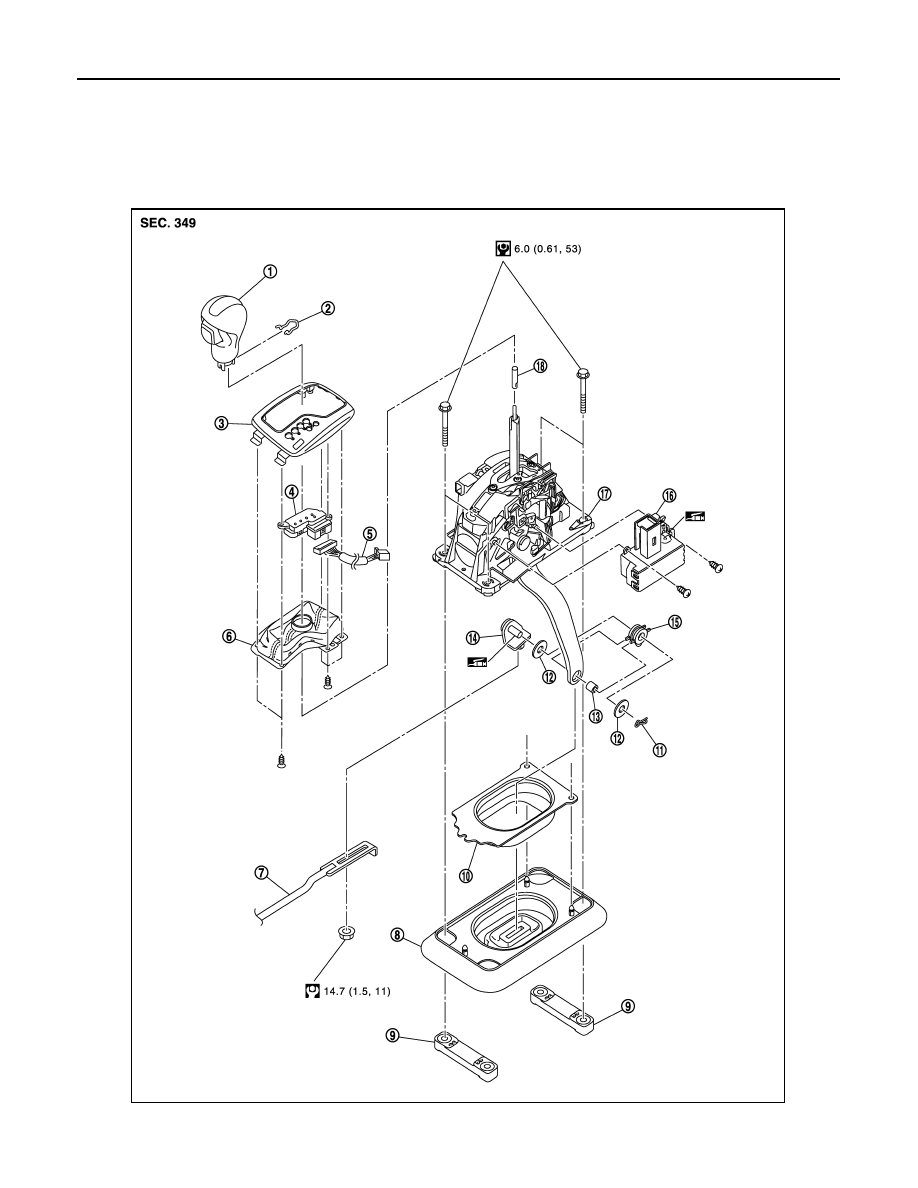
Exploded View
INFOID:0000000005250151
JSDIA1352GB
A/T SHIFT SELECTOR
TM-169
< REMOVAL AND INSTALLATION >
[7AT: RE7R01A (VQ35HR)]
C
E
F
G
H
I
J
K
L
M
A
B
TM
N
O
P
Removal and Installation
INFOID:0000000005250152
REMOVAL
1.
Shift the selector lever to “P” position.
2.
Remove control rod from A/T shift selector.
3.
Shift the selector lever to “N” position.
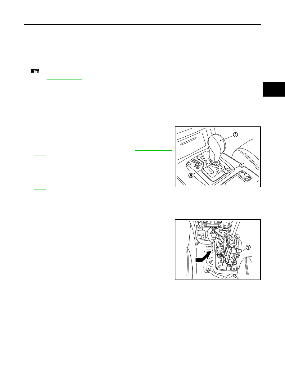
4.
Remove knob cover (A) below selector lever downward.
5.
Pull lock pin (1) out of selector lever knob (2).
6.
Remove selector lever knob.
7.
Remove center console assembly. Refer to
.
CAUTION:
When disconnecting selector lever position indicator con-
nector from shift position switch, never twist or apply an
excessive load to the connector.
8.
Remove rear ventilator duct 1. Refer to
.
9.
Disconnect A/T shift selector harness connector.
10. Remove harness clips from A/T shift selector assembly.
11. Shift the selector lever to “P” position.
12. Remove A/T shift selector assembly mounting bolts.
13. Slightly lift the A/T shift selector assembly (1) and slide it right-
ward. Then pull it out in the diagonally right direction.
14. Remove adapter from A/T shift selector assembly.
15. Remove dust cover and dust cover plate from A/T shift selector
assembly.
16. Remove dust cover from dust cover plate.
17. Remove shift lock unit from A/T shift selector assembly.
18. Remove brackets from vehicle floor panel.
19. Remove selector lever position indicator from console finisher
assembly.
a.
Remove indicator assembly from console finisher assembly.
Refer to
.
b.
Remove insert finisher from indicator assembly.
c.
Remove selector lever position indicator.
INSTALLATION
CAUTION:
Apply multi-purpose grease on the pin surface (that slides after installing a collar) of the pivot pin.
Note the following, and Install in the reverse order of removal.
• Refer to the followings when installing selector lever knob to A/T shift selector assembly.
1.
Insert lock pin to selector lever knob.
2.
Install selector lever knob over selector lever until a click is felt.
CAUTION:
1.
Selector lever knob
2.
Lock pin
3.
Indicator plate
4.
Selector lever position indicator
5.
Harness connector
6.
Insert finisher
7.
Control rod
8.
Dust cover
9.
Bracket
10.
Dust cover plate
11.
Snap pin
12.
Washer
13.
Collar
14.
Pivot pin
15.
Insulator
16.
Shift lock unit
17.
A/T shift selector assembly
18.
Adapter
: Apply multi-purpose grease.
Refer to
for symbols not described on the above.
JPDIA0898ZZ
JPDIA0055ZZ
TM-170
< REMOVAL AND INSTALLATION >
[7AT: RE7R01A (VQ35HR)]
A/T SHIFT SELECTOR
• Install it straight, and never tap or apply any shock to install it.
• Never press selector button.
• When installing control rod to A/T shift selector assembly, refer to “ADJUSTMENT”. Refer to
.
Inspection and Adjustment
INFOID:0000000005250153
INSPECTION AFTER INSTALLATION
Check A/T positions after adjusting A/T positions. Refer to
TM-167, "Inspection and Adjustment"
ADJUSTMENT AFTER INSTALLATION
Adjust A/T positions. Refer to
Нет комментариевНе стесняйтесь поделиться с нами вашим ценным мнением.
Текст