Infiniti FX35, FX50 (S51). Manual — part 194
AV
MULTI AV SYSTEM SYMPTOMS
AV-549
< SYMPTOM DIAGNOSIS >
[NAVIGATION (TWIN MONITOR)]
C
D
E
F
G
H
I
J
K
L
M
B
A
O
P
SYMPTOM DIAGNOSIS
MULTI AV SYSTEM SYMPTOMS
Symptom Table
INFOID:0000000005475453
RELATED TO NAVIGATION
RELATED TO HANDS-FREE PHONE
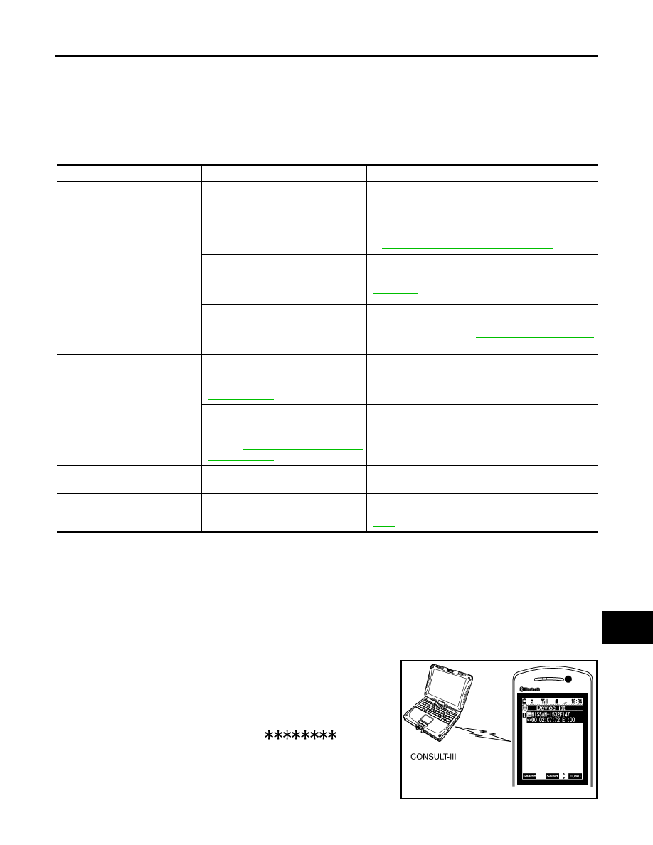
Simple Check for Bluetooth
™
Communication
If cellular phone and AV control unit cannot be connected with Bluetooth
™
communication, following proce-
dure allows the technician to judge which device has malfunction.
1.
Turn ON cellular phone, not connecting Bluetooth
™
communication.
2.
Start CONSULT-III, then start Windows
®
.
3.
Set CONSULT-III near a cellular phone.
4.
When operated Bluetooth
™
registration by cellular phone, check
if CONSULT-III
*
would be displayed on the device name.
(If other Bluetooth
™
device is located near cellular phone, a
name of the device would be displayed also.)
NOTE:
*:Displayed device name is “NISSAN-
”.
• If no device name is displayed, cellular phone is malfunctioning.
Repair the cellular phone first, then perform diagnosis.
• If CONSULT-III is displayed on device name, cellular phone is nor-
mal. Perform diagnosis as per the following table.
Symptoms
Check items
Probable malfunction location
Multifunction switch and preset
switch operation does not work.
• All switches cannot be operated.
• “MULTI AV” is displayed on system
selection screen when the CON-
SULT-III is started.
• Multifunction switch power supply and ground circuit
malfunction.
• AV communication circuit between AV control unit and
multifunction switch.
Perform CONSULT-III self-diagnosis. Refer to
393, "CONSULT - III Function (MULTI AV)"
• All switches cannot be operated.
• “MULTI AV” is not displayed on sys-
tem selection screen when the CON-
SULT-III is initialized.
AV control unit power supply and ground circuit malfunc-
tion. Refer to
AV-510, "AV CONTROL UNIT : Diagnosis
.
Only specified switch cannot be operat-
ed.
Multifunction switch or preset switch malfunction.
Perform multifunction switch and preset switch self-di-
agnosis function. Refer to
.
Fuel economy display is abnor-
mal.
There is malfunction in the CONSULT-
III “self-diagnosis result” of “MULTI AV”.
Refer to
.
Perform detected DTC diagnosis.
Refer to
AV-393, "CONSULT - III Function (MULTI AV)"
There is no malfunction in the CON-
SULT-III “self-diagnosis results” of
“MULTI AV”.
Refer to
.
Ignition signal circuit malfunction.
Start of the AV control unit takes
time.
—
Front door switch signal circuit malfunction.
Guide sound is not heard or too
low.
On the setting display select “system
sound (guide sound volume, etc.),” and
confirm that guide sound is ON.
AV control unit malfunction.
Replace AV control unit. Refer to
JPNIA0441GB
AV-550
< SYMPTOM DIAGNOSIS >
[NAVIGATION (TWIN MONITOR)]
MULTI AV SYSTEM SYMPTOMS
RELATED TO AROUND VIEW MONITOR
Symptoms
Check items
Probable malfunction location
Does not recognize cellular
phone connection. (no connec-
tion is displayed on the display
at the guide.)
Repeat the registration of cellular phone.
AV control unit malfunction.
Replace AV control unit. Refer to
Hands-free phone cannot be
established.
• Hands-free phone operation can be
made, but the communication cannot
be established.
• Hands-free phone operation can be
performed, however, voice between
each other cannot be heard during the
conversation.
AV control unit malfunction.
Replace AV control unit. Refer to
The other party's voice cannot
be heard by hands-free phone.
Check the “microphone speaker” in In-
spection & Adjustment Mode if sound is
heard.
AV control unit malfunction.
Replace AV control unit. Refer to
Originating sound is not heard
by the other party with hands-
free phone communication.
Sound operation function is normal.
AV control unit malfunction.
Replace AV control unit. Refer to
Sound operation function does not work.
Microphone signal circuit malfunction.
Refer to
.
The system cannot be operat-
ed.
Steering switch's ”VOL UP”, “VOL
DOWN”, “
” switch works, but “
” it
does not work.
Steering switch malfunction.
Replace steering switch. Refer to
Steering switch's “
”, ”VOL UP”, “VOL
DOWN”, “
” switches do not work.
Steering switch signal B circuit malfunction.
Refer to
.
All steering switches do not work.
Steering switch ground circuit malfunction.
Refer to
.
Symptoms
Check items
Probable malfunction location / Action
to take
It does not switch to camera image
even when the “CAMERA” switch is
pressed or the selector lever is in the
reverse position.
“Camera Cont.” of “Confirmation/Adjustment” can be
selected.
Ignition signal circuit malfunction
(around view monitor control unit).
“Camera Cont.” of “Confirmation/Adjustment” cannot
be selected.
• Around view monitor control unit
power supply and ground circuits
malfunction.
Refer to
MONITOR CONTROL UNIT : Diag-
nosis Procedure"
.
• AV communication circuits malfunc-
tion.
Refer to
The screen switches when pressing
the “CAMERA” switch or shifting the
selector lever to the reverse posi-
tion, however, all views are not dis-
played.
Only superimposing is displayed.
(Only the image displayed by AV control unit is dis-
played)
Camera image signal circuit between
around view monitor control unit and
display unit malfunction.
Refer to
.
Superimposing is not displayed.
Communication circuit between AV
control unit and display unit malfunc-
tion.
Refer to
Camera image is rolling.
—
Communication circuit between AV
control unit and display unit malfunc-
tion.
Refer to

AV
MULTI AV SYSTEM SYMPTOMS
AV-551
< SYMPTOM DIAGNOSIS >
[NAVIGATION (TWIN MONITOR)]
C
D
E
F
G
H
I
J
K
L
M
B
A
O
P
RELATED TO CAMERA ASSISTANCE SONAR
It cannot be switched to rear view
monitor even when the selector le-
ver is in the reverse position.
The front view is displayed normally.
Reverse signal circuit malfunction. (AV
control unit)
The predicted course line display in
front view and rear view is malfunc-
tioning.
The “Steer. Angle Sensor” is not turned ON at “Con-
nection Confirmation” of “Camera Cont.”
Steering angle sensor signal circuits.
• The front view screen is not dis-
played.
• The front of Birds-Eye view
screen is not displayed.
Check the item Front
Camera in “Connec-
tion Confirmation”
mode of “Camera
Cont.”
• Image Output Signal: NG
• COMM Status: NG
• COMM Line: NG
• Front camera image signal circuit
malfunction.
• Front camera power supply and
ground circuits malfunction.
Refer to
.
• Image Output Signal: OK
• COMM Status: NG
• COMM Line: NG
Front camera communication signal cir-
cuit malfunction. Refer to
• The rear view screen is not dis-
played.
• The rear of Birds-Eye view screen
is not displayed.
Check the item Rear
Camera in “Connec-
tion Confirmation”
mode of “Camera
Cont.”
• Image Output Signal: NG
• COMM Status: NG
• COMM Line: NG
• Rear camera image signal circuit
malfunction.
• Rear camera power supply and
ground circuits malfunction.
Refer to
.
• Image Output Signal: OK
• COMM Status: NG
• COMM Line: NG
Rear camera communication signal cir-
cuits malfunction. Refer to
• The front-side screen is not dis-
played.
• The passenger side of Birds-Eye
view screen is not displayed.
Check the item Pass-
Side Camera in “Con-
nection Confirmation”
mode of “Camera
Cont.”
• Image Output Signal: NG
• COMM Status: NG
• COMM Line: NG
• Side camera RH image signal circuit
malfunction.
• Side camera RH power supply and
ground circuits malfunction.
Refer to
• Image Output Signal: OK
• COMM Status: NG
• COMM Line: NG
• Side camera RH communication cir-
cuit malfunction. Refer to
The driver side of Birds-eye view
screen is not displayed.
Check the item Dr-
Side Camera at “Con-
nection Confirmation”
mode of “Camera
Cont.”
• Image Output Signal: NG
• COMM Status: NG
• COMM Line: NG
• Side camera LH image signal circuit
malfunction.
• Side camera LH power supply and
ground circuits malfunction.
Refer to
• Image Output Signal: OK
• COMM Status: NG
• COMM Line: NG
• Side camera LH communication cir-
cuit malfunction. Refer to
When shift position is other than “R”
the front-side and front screen or the
Birds-Eye view and front screen re-
main displaying even if the vehicle
speed increases.
—
Vehicle speed signal circuit malfunction
(around view monitor control unit).
Symptoms
Check items
Probable malfunction location / Action
to take
AV-552
< SYMPTOM DIAGNOSIS >
[NAVIGATION (TWIN MONITOR)]
MULTI AV SYSTEM SYMPTOMS
RELATED TO RGB IMAGE
RELATED TO VOICE CONTROL
RELATED TO AUDIO
Symptoms
Check items
Probable malfunction location / Action to
take
The malfunction is detected in the sonar in-
dicator
(Always displayed in red)
The malfunction is detected in only 1 indica-
tor (Always displayed in red).
• Corner sensor malfunction in corre-
sponding area.
• Corner sensor harness circuit in corre-
sponding area.
Perform CONSULT-III “self-diagnosis” of
“SONAR”. Refer to
.
The malfunction is detected in all 4 indicators
(Always displayed in red).
• Corner sensor ground circuit malfunc-
tion.
Perform CONSULT-III “self-diagnosis” of
“SONAR”. Refer to
.
• Sonar control unit power supply and
ground circuits malfunction.
• AV communication circuits malfunc-
tion.
Perform CONSULT-III “self-diagnosis” of
“MULTI AV”. Refer to
.
The sonar indicator is normal, but the buzz-
er does not sound
—
Replace sonar control unit. Refer to
Symptoms
Check items
Probable malfunction location
RGB image is not shown.
—
RGB digital image signal circuit malfunction.
Refer to
.
Symptoms
Check items
Probable malfunction location
The voice cannot be controlled
even if the voice control screen
is displayed.
Voice sounds at “Voice Microphone Test”
of Confirmation/Adjustment mode.
AV control unit malfunction.
Replace AV control unit. Refer to
.
Voice does not sound at “Voice Micro-
phone Test” of Confirmation/Adjustment
mode.
Microphone circuit malfunction.
Refer to
.
The voice cannot be controlled
(Voice control screen is not dis-
played).
Steering switch's “SOURCE”, “MENU
UP”, “MENU DOWN”, “ENTER” switch
works, but “
” it does not work.
Steering switch malfunction.
Replace steering switch. Refer to
.
Steering switch's “SOURCE”, “MENU
UP”, “MENU DOWN”, “
”, “ENTER”
switches do not work.
Steering switch signal A circuit malfunction.
Refer to
.
All steering switches do not work.
Steering switch ground circuit malfunction.
Refer to
.
Symptoms
Check items
Probable malfunction location
The disk cannot be removed.
—
Disk eject signal circuit malfunction.
Refer to
.
Нет комментариевНе стесняйтесь поделиться с нами вашим ценным мнением.
Текст