Infiniti FX35, FX50 (S51). Manual — part 1089

NOISE, VIBRATION AND HARSHNESS (NVH) TROUBLESHOOTING
FSU-3
< SYMPTOM DIAGNOSIS >
[2WD]
C
D
F
G
H
I
J
K
L
M
A
B
FSU
N
O
P
SYMPTOM DIAGNOSIS
NOISE, VIBRATION AND HARSHNESS (NVH) TROUBLESHOOTING
NVH Troubleshooting Chart
INFOID:0000000005246407
Use chart below to find the cause of the symptom. If necessary, repair or replace these parts.
×
: Applicable
Reference page
,
,
,
,
—
—
—
,
,
,
,
NV
H
in
D
L
N
s
e
c
ti
o
n
NV
H
in
F
A
X
an
d F
S
U
s
e
c
tio
n
NV
H
in
WT s
e
cti
on
NV
H
in
B
R
s
e
c
tio
n
NV
H
in
S
T
s
e
c
ti
o
n
Possible cause and SUSPECTED PARTS
Im
prop
er ins
ta
lla
ti
on,
lo
os
en
es
s
Sh
oc
k ab
so
rbe
r de
fo
rma
tio
n,
da
ma
ge
or de
fl
e
ct
ion
Bu
sh
in
g o
r
m
o
u
n
ti
ng
de
te
ri
ora
ti
o
n
Part
s interference
S
p
ring
fa
tig
u
e
Su
sp
en
si
on
lo
os
en
es
s
Inc
o
rre
c
t whe
e
l al
ig
nm
en
t
S
ta
b
iliz
er ba
r
fa
tig
u
e
PROPELLER SHAF
T
FRONT AXLE AND F
R
ONT
SUSPENSI
ON
ROA
D
WHEEL
BRAKE
STEERI
N
G
Symptom
FRONT SUSPENSION
Noise
×
×
×
×
×
×
×
×
×
×
×
Shake
×
×
×
×
×
×
×
×
×
×
Vibration
×
×
×
×
×
×
×
×
Shimmy
×
×
×
×
×
×
×
×
×
Judder
×
×
×
×
×
×
×
Poor quality ride or handling
×
×
×
×
×
×
×
×
×
FSU-4
< PRECAUTION >
[2WD]
PRECAUTIONS
PRECAUTION
PRECAUTIONS
Precaution for Supplemental Restraint System (SRS) "AIR BAG" and "SEAT BELT
PRE-TENSIONER"
INFOID:0000000005548668
The Supplemental Restraint System such as “AIR BAG” and “SEAT BELT PRE-TENSIONER”, used along
with a front seat belt, helps to reduce the risk or severity of injury to the driver and front passenger for certain
types of collision. This system includes seat belt switch inputs and dual stage front air bag modules. The SRS
system uses the seat belt switches to determine the front air bag deployment, and may only deploy one front
air bag, depending on the severity of a collision and whether the front occupants are belted or unbelted.
Information necessary to service the system safely is included in the “SRS AIR BAG” and “SEAT BELT” of this
Service Manual.
WARNING:
• To avoid rendering the SRS inoperative, which could increase the risk of personal injury or death in
the event of a collision which would result in air bag inflation, all maintenance must be performed by
an authorized NISSAN/INFINITI dealer.
• Improper maintenance, including incorrect removal and installation of the SRS, can lead to personal
injury caused by unintentional activation of the system. For removal of Spiral Cable and Air Bag
Module, see the “SRS AIR BAG”.
• Do not use electrical test equipment on any circuit related to the SRS unless instructed to in this
Service Manual. SRS wiring harnesses can be identified by yellow and/or orange harnesses or har-
ness connectors.
PRECAUTIONS WHEN USING POWER TOOLS (AIR OR ELECTRIC) AND HAMMERS
WARNING:
• When working near the Air Bag Diagnosis Sensor Unit or other Air Bag System sensors with the
ignition ON or engine running, DO NOT use air or electric power tools or strike near the sensor(s)
with a hammer. Heavy vibration could activate the sensor(s) and deploy the air bag(s), possibly
causing serious injury.
• When using air or electric power tools or hammers, always switch the ignition OFF, disconnect the
battery, and wait at least 3 minutes before performing any service.
Precaution Necessary for Steering Wheel Rotation after Battery Disconnect
INFOID:0000000005548671
NOTE:
• Before removing and installing any control units, first turn the push-button ignition switch to the LOCK posi-
tion, then disconnect both battery cables.
• After finishing work, confirm that all control unit connectors are connected properly, then re-connect both
battery cables.
• Always use CONSULT-III to perform self-diagnosis as a part of each function inspection after finishing work.
If a DTC is detected, perform trouble diagnosis according to self-diagnosis results.
For vehicle with steering lock unit, if the battery is disconnected or discharged, the steering wheel will lock and
cannot be turned.
If turning the steering wheel is required with the battery disconnected or discharged, follow the operation pro-
cedure below before starting the repair operation.
OPERATION PROCEDURE
1.
Connect both battery cables.
NOTE:
Supply power using jumper cables if battery is discharged.
2.
Turn the push-button ignition switch to ACC position.
(At this time, the steering lock will be released.)
3.
Disconnect both battery cables. The steering lock will remain released with both battery cables discon-
nected and the steering wheel can be turned.
4.
Perform the necessary repair operation.
PRECAUTIONS
FSU-5
< PRECAUTION >
[2WD]
C
D
F
G
H
I
J
K
L
M
A
B
FSU
N
O
P
5.
When the repair work is completed, re-connect both battery cables. With the brake pedal released, turn
the push-button ignition switch from ACC position to ON position, then to LOCK position. (The steering
wheel will lock when the push-button ignition switch is turned to LOCK position.)
6.
Perform self-diagnosis check of all control units using CONSULT-III.
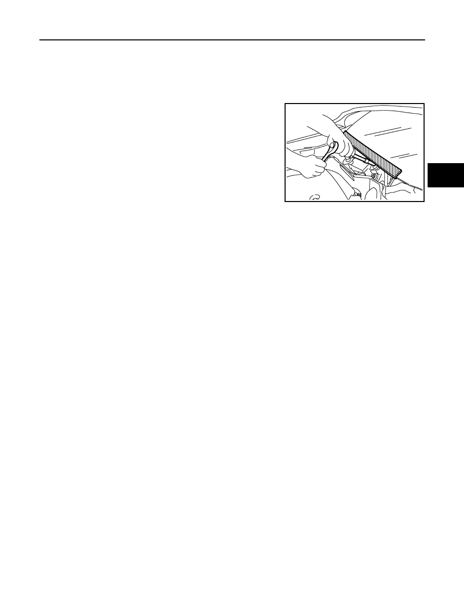
Precaution for Procedure without Cowl Top Cover
INFOID:0000000005548673
When performing the procedure after removing cowl top cover, cover
the lower end of windshield with urethane, etc.
Precautions for Suspension
INFOID:0000000005246411
CAUTION:
• When installing rubber bushings, the final tightening must be carried out under unladen conditions
with tires on ground. Spilled oil might shorten the life of rubber bushings. Be sure to wipe off any
spilled oil.
- Unladen conditions mean that fuel, engine coolant and lubricant are full. Spare tire, jack, hand tools
and mats are in designated positions.
• After servicing suspension parts, be sure to check wheel alignment.
• Self-lock nuts are not reusable. Always use new ones when installing. Since new self-lock nuts are
pre-oiled, tighten as they are.
PIIB3706J

FSU-6
< PREPARATION >
[2WD]
PREPARATION
PREPARATION
PREPARATION
Special Service Tool
INFOID:0000000005246412
The actual shapes of Kent-Moore tools may differ from those of special service tools illustrated here.
Commercial Service Tool
INFOID:0000000005246413
Tool number
(Kent-Moore No.)
Tool name
Description
ST35652000
(
–
)
Shock absorber attachment
Disassembling and assembling shock
absorber
ST3127S000
(J-25765-A)
Preload gauge
Measuring rotating torque of ball joint
ZZA0807D
ZZA0806D
Tool name
Description
Power tool
Loosening bolts and nuts
Spring compressor
Removing and installing coil spring
PBIC0190E
S-NT717
Нет комментариевНе стесняйтесь поделиться с нами вашим ценным мнением.
Текст