Infiniti I35 (A33). Manual — part 358
MEL158P
MEL159P
Replacement
For removal and installation of spiral cable, refer to RS-20,
“Installation — Air Bag Module and Spiral Cable”.
I
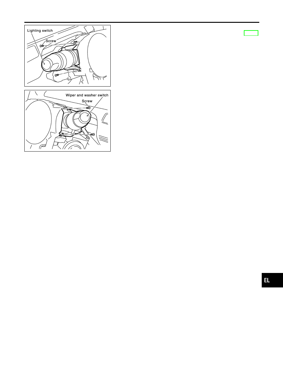
Each switch can be replaced without removing spiral cable.
1.
Remove the instrument lower panel on driver side.
2.
Remove the steering column cover.
3.
Remove lighting switch or wiper and washer switch mounting
screw.
4.
Remove lighting switch or wiper and washer switch from the
spiral cable.
5.
Disconnect lighting switch or wiper and washer switch connec-
tor.
GI
MA
EM
LC
EC
FE
AT
AX
SU
BR
ST
RS
BT
HA
SC
IDX
COMBINATION SWITCH
Replacement
EL-33
Check
NHEL0011
MEL243O
STEERING SWITCH
Check
EL-34
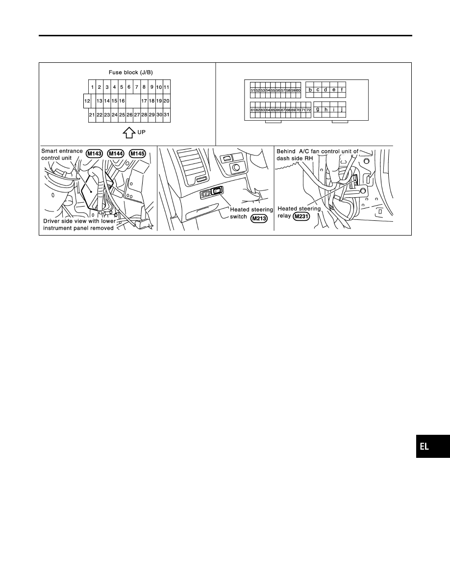
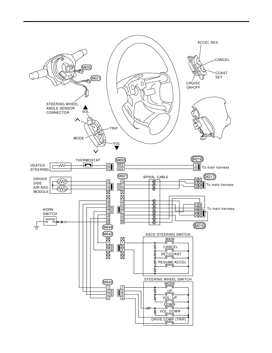
Component Parts and Harness Connector
Location
NHEL0314
SEL452YA
System Description
NHEL0315
The heated steering system is controlled by the smart entrance control unit. The heated steering system
operates only for approximately 30 minutes after heated steering switch is turned “ON”.
Then the heated steering system is turned “OFF” when the heated steering switch is turned “ON” again or
ignition switch “OFF” within 30 minutes after heated steering system “ON”.
Power is supplied at all times
I
to smart entrance control unit terminal 49
I
through 10A fuse [No. 13, located in the fuse block (J/B)]
I
to heated steering relay terminal 3
I
through 10A fuse (No. 72, located in the fuse and fusible link box)
With the ignition switch in the ON or START position, power is supplied.
I
through 10A fuse [No. 10, located in the fuse block (J/B)]
I
to the heated steering relay terminal 1 and
I
to smart entrance control unit terminal 27.
Ground is supplied
I
to terminal 2 and 5 of heated steering switch and
I
to combination switch (heated steering switch) terminal 2
I
through body grounds M9, M25 and M87.
When the heated steering switch is turned ON, ground is supplied
I
through terminal 1 of heated steering switch
I
to smart entrance control unit terminal 4.
Terminal 40 of the smart entrance control unit then supplies ground to the heated steering relay terminal 2.
With power and ground supplied, the heated steering relay is energized.
Power is supplied
I
through terminal 5 of heated steering relay
I
to heated steering switch terminal 4 and
I
to combination switch (heated steering switch) terminal 1.
I
through terminal 3 of combination switch (heated steering switch)
I
to the heated steering (thermostat).
Ground is supplied for heated steering
I
through heated steering
GI
MA
EM
LC
EC
FE
AT
AX
SU
BR
ST
RS
BT
HA
SC
IDX
HEATED STEERING
Component Parts and Harness Connector Location
EL-35
I
to combination switch (heated steering switch) terminal 4.
With power and ground supplied, the heated steering heats.
When the system is activated, the heated steering indicator lamp illuminates in the heated steering switch.
HEATED STEERING
System Description (Cont’d)
EL-36
Нет комментариевНе стесняйтесь поделиться с нами вашим ценным мнением.
Текст