Infiniti I35 (A33). Manual — part 181
16
CHECK TIMING CHAIN INSTALLATION
Check timing chain installation. Refer to EM-29, “TIMING CHAIN”.
OK or NG
OK
©
GO TO 17.
NG
©
1. Repair the timing chain installation.
2. GO TO 4.
17
DETECT MALFUNCTIONING PART
Check the following.
I
Check camshaft position sensor (PHASE) and circuit. Refer to “DTC P0340, P0345 CMP SENSOR (PHASE)”, EC-323.
I
Check crankshaft position sensor (POS) and circuit. Refer to “DTC P0335 CKP SENSOR (POS)”, EC-316.
OK or NG
OK
©
GO TO 18.
NG
©
1. Repair or replace.
2. GO TO 4.
18
CHECK ECM FUNCTION
1. Substitute another known-good ECM to check ECM function. (ECM may be the cause of an incident, but this is a rare
case.)
2. Perform initialization of IVIS (NATS) system and registration of all IVIS (NATS) ignition key IDs. Refer to “IVIS (INFINITI
VEHICLE IMMOBILIZER SYSTEM — NATS)”, EC-90.
©
GO TO 4.
19
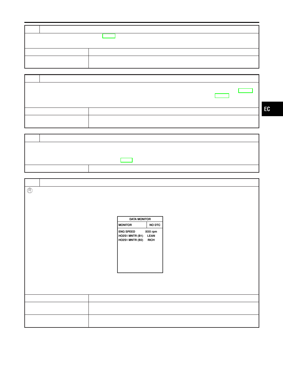
CHECK HEATED OXYGEN SENSOR 1 (BANK 1) SIGNAL
With CONSULT-II
1. Run engine at about 2,000 rpm for about 2 minutes under no-load.
2. See “HO2S1 MNTR (B1)” in “DATA MONITOR” mode.
3. Running engine at 2,000 rpm under no-load (The engine is warmed up to normal operating temperature.), check that
the monitor fluctuates between LEAN and RICH more than 5 times during 10 seconds.
PBIB0120E
1 time: RICH
→
LEAN
→
RICH
2 times: RICH
→
LEAN
→
RICH
→
LEAN
→
RICH
OK or NG
OK
©
GO TO 21.
NG (Monitor does not
fluctuate.)
©
GO TO 23.
NG (Monitor fluctuates
less than 5 times.)
©
GO TO 30.
GI
MA
EM
LC
FE
AT
AX
SU
BR
ST
RS
BT
HA
SC
EL
IDX
BASIC SERVICE PROCEDURE
Idle Speed/Ignition Timing/Idle Mixture Ratio Adjustment (Cont’d)
EC-65
20
CHECK HEATED OXYGEN SENSOR 1 (BANK 1) SIGNAL
Without CONSULT-II
1. Stop engine and set ECM to Self-diagnostic mode II (Heated oxygen sensor 1 monitor). Refer to “HOW TO SWITCH
DIAGNOSTIC TEST MODE”, EC-91.
2. Start engine and run it at about 2,000 rpm for about 2 minutes under no-load.
3. Running engine at 2,000 rpm under no-load (The engine is warmed up to normal operating temperature.), check that
the MIL comes on more than 5 times during 10 seconds.
OK or NG
OK
©
GO TO 22.
NG (MIL does not come
on)
©
GO TO 23.
NG (MIL comes on less
than 5 times)
©
GO TO 30.
21
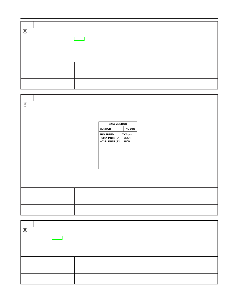
CHECK HEATED OXYGEN SENSOR 1 (BANK 2) SIGNAL
With CONSULT-II
1. See “HO2S1 MNTR (B2)” in “DATA MONITOR” mode.
2. Running engine at 2,000 rpm under no-load (The engine is warmed up to normal operating temperature.), check that
the monitor fluctuates between LEAN and RICH more than 5 times during 10 seconds.
PBIB0120E
1 time: RICH
→
LEAN
→
RICH
2 times: RICH
→
LEAN
→
RICH
→
LEAN
→
RICH
OK or NG
OK
©
INSPECTION END
NG (Monitor does not
fluctuate.)
©
GO TO 24.
NG (Monitor fluctuates
less than 5 times.)
©
GO TO 31.
22
CHECK HEATED OXYGEN SENSOR 1 (BANK 2) SIGNAL
Without CONSULT-II
1. Switch the monitored sensor from bank 1 to bank 2. Refer to “How to Switch Monitored Sensor from Bank 1 to Bank 2
or Vice Versa”, EC-92.
2. Running engine at 2,000 rpm under no-load (The engine is warmed up to normal operating temperature.), check that
the MIL comes on more than 5 times during 10 seconds.
OK or NG
OK
©
INSPECTION END
NG (MIL does not come
on)
©
GO TO 24.
NG (MIL comes on less
than 5 times)
©
GO TO 31.
BASIC SERVICE PROCEDURE
Idle Speed/Ignition Timing/Idle Mixture Ratio Adjustment (Cont’d)
EC-66
23
CHECK HEATED OXYGEN SENSOR 1 (BANK 1) HARNESS
1. Turn ignition switch OFF and disconnect battery ground cable.
2. Disconnect ECM harness connector.
3. Disconnect heated oxygen sensor 1 (bank 1) harness connector.
4. Check harness continuity between ECM terminal 91 and heated oxygen sensor 1 (bank 1) terminal 1. Refer to “Wiring
Diagram”, EC-250
Continuity should exist.
5. Also check harness for short to ground and short to power.
OK or NG
OK
©
GO TO 25.
NG
©
1. Repair or replace harness between ECM and heated oxygen sensor 1 (bank 1).
2. GO TO 4.
24
CHECK HEATED OXYGEN SENSOR 1 (BANK 2) HARNESS
1. Turn ignition switch OFF and disconnect battery ground cable.
2. Disconnect ECM harness connector.
3. Disconnect heated oxygen sensor 1 (bank 2) harness connector.
4. Check harness continuity between ECM terminal 92 and heated oxygen sensor 1 (bank 2) terminal 1. Refer to “Wiring
Diagram”, EC-251.
Continuity should exist.
5. Also check harness for short to ground and short to power.
OK or NG
OK
©
GO TO 25.
NG
©
1. Repair or replace harness between ECM and heated oxygen sensor 1 (bank 2).
2. GO TO 4.
25
PERFORM ACCELERATOR PEDAL RELEASED POSITION LEARNING
1. Reconnect ECM harness connector.
2. Perform “Accelerator pedal released position learning”, EC-70.
©
GO TO 26.
26
PERFORM THROTTLE VALVE CLOSED POSITION LEARNING
Perform “Throttle Valve Closed Position Learning”, EC-70.
©
GO TO 27.
27
PERFORM IDLE AIR VOLUME LEARNING
Perform “Idle Air Volume Learning”, EC-70.
Is Idle Air Volume Learning carried out successfully?
Yes or No
Yes (With CONSULT-II)
©
GO TO 28.
Yes (Without CONSULT-
II)
©
GO TO 29.
No
©
1. Follow the instruction of Idle Air Volume Learning.
2. GO TO 4.
GI
MA
EM
LC
FE
AT
AX
SU
BR
ST
RS
BT
HA
SC
EL
IDX
BASIC SERVICE PROCEDURE
Idle Speed/Ignition Timing/Idle Mixture Ratio Adjustment (Cont’d)
EC-67
28
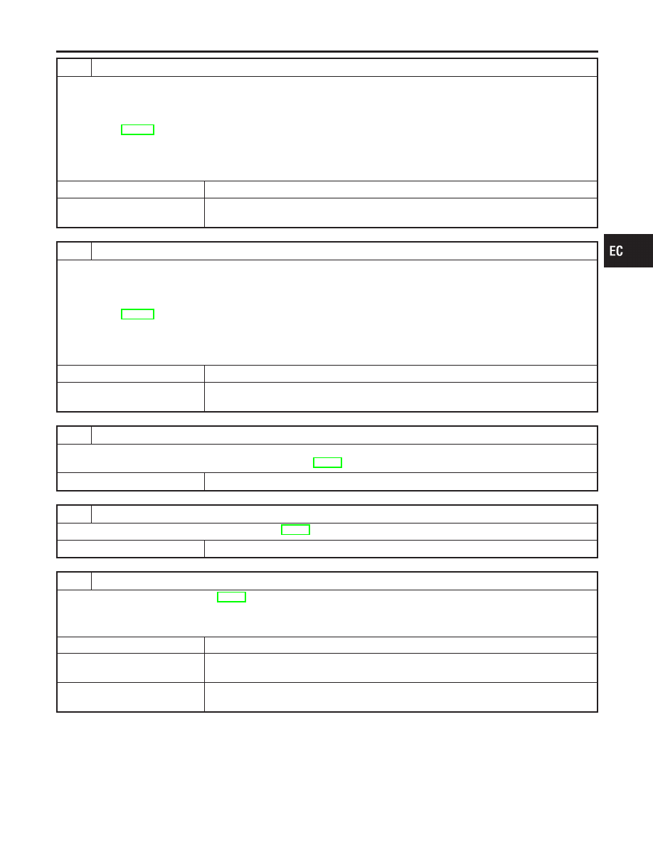
CHECK CO %
With CONSULT-II
1. Start engine and warm it up until engine coolant temperature indicator points to the middle of gauge.
2. Turn ignition switch OFF, wait at least 10 seconds and then turn ON.
3. Select “ENG COOLANT TEMP” in “ACTIVE TEST” mode.
4. Set “ENG COOLANT TEMP” to 5°C (41°F) by touching “DWN” and “Qd”.
5. Start engine and rev it (2,000 to 3,000 rpm) two or three times under no-load, then run engine at idle speed.
6. Check CO %.
SEF172Y
Idle CO: 0.7 - 9.9 % and engine runs smoothly.
OK or NG
OK
©
GO TO 31.
NG
©
GO TO 30.
29
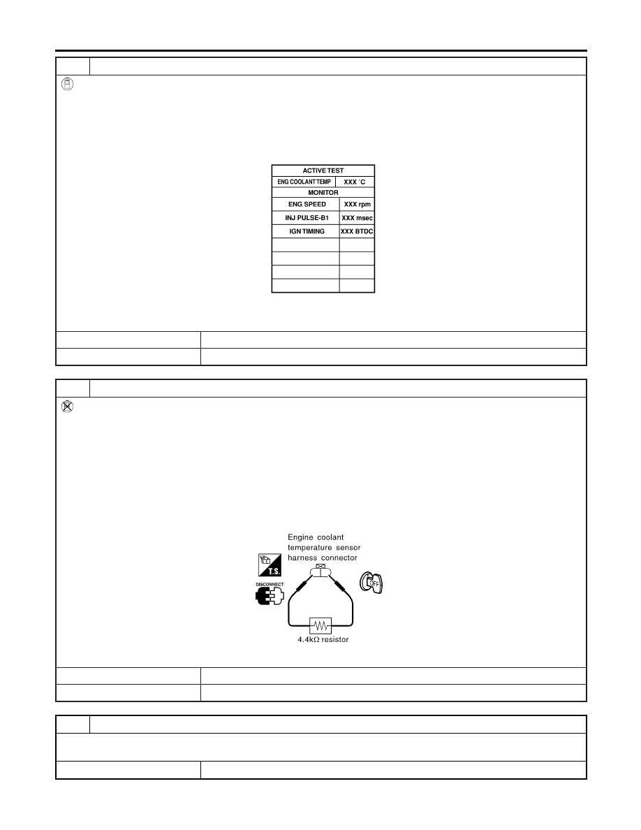
CHECK CO %
Without CONSULT-II
1. Start engine and warm it up until engine coolant temperature indicator points to the middle of gauge.
2. Turn ignition switch OFF.
3. Disconnect engine coolant temperature sensor harness connector.
4. Connect a resistor (4.4 k
Ω
) between terminals of engine coolant temperature sensor harness connector.
5. Start engine and rev it (2,000 to 3,000 rpm) two or three times under no-load, then run engine at idle speed.
6. Check CO %.
Idle CO: 0.7 - 9.9 % and engine runs smoothly.
7. After checking CO %, turn ignition switch OFF, disconnect the resistor from the terminals of engine coolant temperature
sensor harness connector, and then connect engine coolant temperature sensor harness connector to engine coolant
temperature sensor.
SEF982UA
OK or NG
OK
©
GO TO 31.
NG
©
GO TO 30.
30
RECONNECT HEATED OXYGEN SENSOR 1 HARNESS CONNECTOR
1. Turn ignition switch OFF.
2. Reconnect heated oxygen sensor 1 harness connector.
©
GO TO 34.
BASIC SERVICE PROCEDURE
Idle Speed/Ignition Timing/Idle Mixture Ratio Adjustment (Cont’d)
EC-68
Нет комментариевНе стесняйтесь поделиться с нами вашим ценным мнением.
Текст