Infiniti I35 (A33). Manual — part 53
Diagnostic Procedure
NHAT0084
1
CHECK INPUT SIGNAL
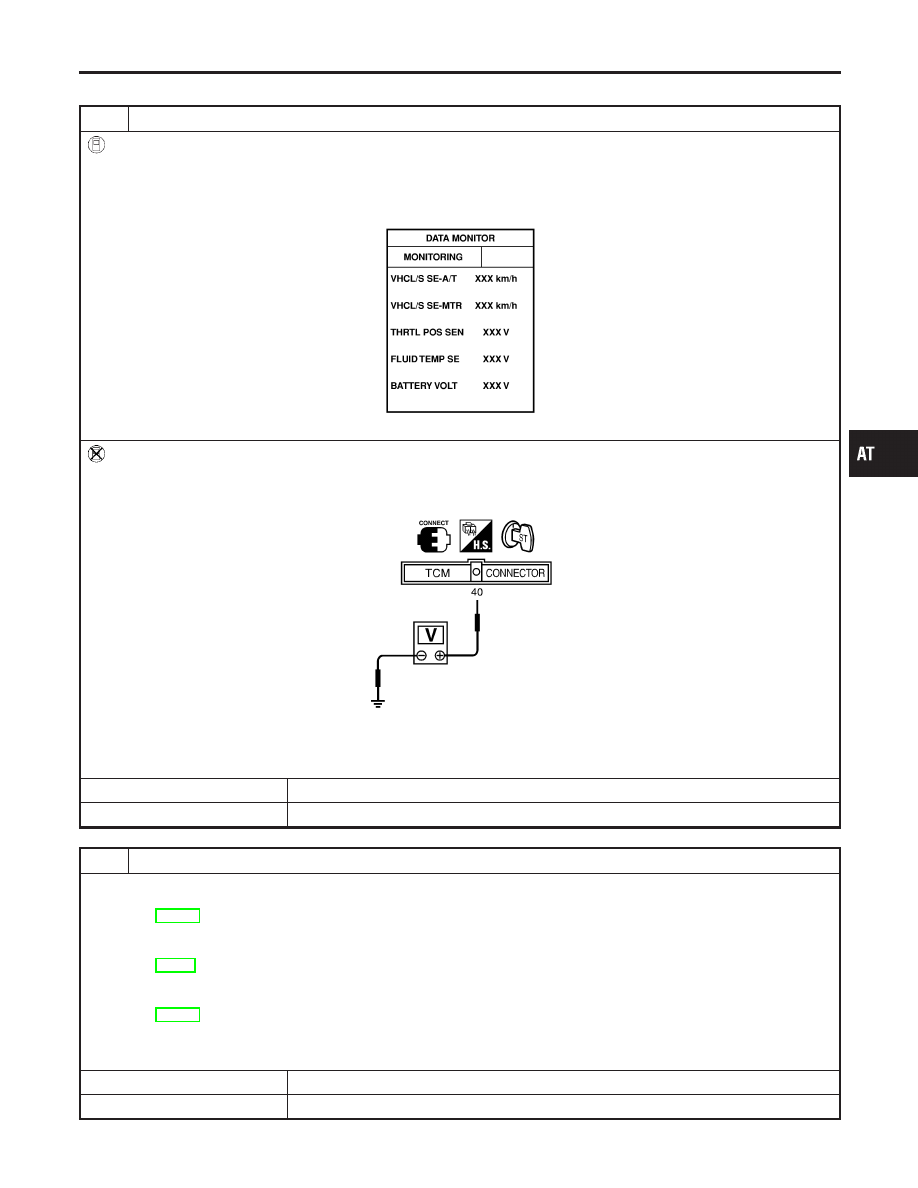
With CONSULT-II
1. Start engine.
2. Select “TCM INPUT SIGNALS” in “DATA MONITOR” mode for “A/T” with CONSULT-II.
3. Read out the value of “VHCL/S SE·MTR” while driving.
Check the value changes according to driving speed.
SAT614J
Without CONSULT-II
1. Start engine.
2. Check voltage between TCM harness connector F50 terminal 40 (PU/R) and ground while driving at 2 to 3 km/h (1 to 2
MPH) for 1 m (3 ft) or more.
SAT356JB
Voltage:
Intermittently changes between approx. 0V and approx. 4.5V.
OK or NG
OK
©
GO TO 3.
NG
©
GO TO 2.
2
DETECT MALFUNCTIONING ITEM
Check the following items:
I
Combination meter
Refer to EL-125, “METERS AND GAUGES”.
I
Harness for short or open between TCM and combination meter
I
ABS/TCS control unit (with TCS)
Refer to BR-46, “ON BOARD DIAGNOSTIC SYSTEM DESCRIPTION”.
I
Harness for short or open between combination meter and ABS/TCS control unit (with TCS)
I
Vehicle speed sensor and ground circuit for vehicle speed sensor (with VDC)
Refer to EL-125, “METERS AND GAUGES”.
I
Harness for short or open between combination meter and vehicle speed sensor (with VDC)
OK or NG
OK
©
GO TO 3.
NG
©
Repair or replace damaged parts.
GI
MA
EM
LC
EC
FE
AX
SU
BR
ST
RS
BT
HA
SC
EL
IDX
DTC VEHICLE SPEED SENSOR·MTR
Diagnostic Procedure
AT-209
3
CHECK DTC
Perform Diagnostic Trouble Code (DTC) confirmation procedure, AT-207.
OK or NG
OK
©
INSPECTION END
NG
©
GO TO 4.
4
CHECK TCM INSPECTION
1. Perform TCM input/output signal inspection.
2. If NG, recheck TCM pin terminals for damage or loose connection with harness connector.
OK or NG
OK
©
INSPECTION END
NG
©
Repair or replace damaged parts.
DTC VEHICLE SPEED SENSOR·MTR
Diagnostic Procedure (Cont’d)
AT-210
SAT576K
Description
NHAT0272
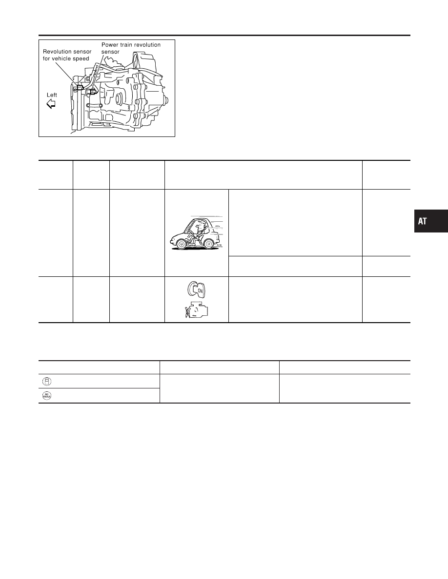
The power train revolution sensor detects foward clutch drum rpm
(revolutions per minute). It is located on the input side of the auto-
matic transmission. The vehicle speed sensor A/T (Revolution sen-
sor) is located on the output side of the automatic transmission.
With the two sensors, input and output shaft rpms are accurately
detected. The result is optimal shift timing during deceleration and
improved shifting.
TCM TERMINALS AND REFERENCE VALUE
NHAT0272S01
Remarks: Specification data are reference values.
Terminal
No.
Wire color
Item
Condition
Judgement
standard
(Approx.)
38
PU
Power train revo-
lution sensor
When moving at 20 km/h (12 MPH), use the
CONSULT-II pulse frequency measuring func-
tion.*1
CAUTION:
Connect the diagnosis data link cable to
the vehicle diagnosis connector.
*1: A circuit tester cannot be used to test this
item.
240 Hz
When vehicle parks.
Under 1.3V or
over 4.5V
42
B
Sensor ground
—
0V
On Board Diagnosis Logic
NHAT0279
Diagnostic trouble code
Malfunction is detected when ...
Check item (Possible cause)
: TURBINE REV
TCM does not receive the proper voltage
signal from the sensor.
I
Harness or connectors
(The sensor circuit is open or shorted.)
I
Power train revolution sensor
: 10th judgement flicker
GI
MA
EM
LC
EC
FE
AX
SU
BR
ST
RS
BT
HA
SC
EL
IDX
DTC POWER TRAIN REVOLUTION SENSOR
Description
AT-211
SAT014K
Diagnostic Trouble Code (DTC) Confirmation
Procedure
=NHAT0277
SAT860K
SAT552K
CAUTION:
I
Always drive vehicle at a safe speed.
I
If conducting this “DTC CONFIRMATION PROCEDURE”
again, always turn ignition switch “OFF” and wait at least
5 seconds before continuing.
After the repair, perform the following procedure to confirm the
malfunction is eliminated.
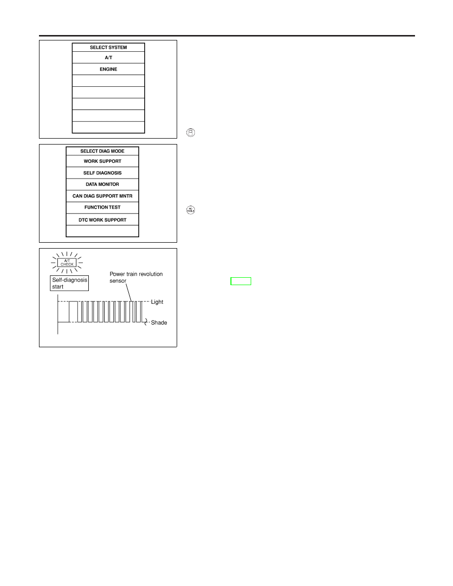
WITH CONSULT-II
NHAT0277S01
1)
Start engine.
2)
Select “DATA MONITOR” mode for “A/T” with CONSULT-II.
3)
Drive vehicle under the following conditions:
Selector lever in “D”, vehicle speed higher than 40 km/h (25
MPH), engine speed higher than 1,500 rpm, throttle opening
greater than 1.0/8 of the full throttle position and driving for
more than 5 seconds.
NO TOOLS
NHAT0277S02
1)
Start engine.
2)
Drive vehicle under the following conditions:
Selector lever in “D”, vehicle speed higher than 40 km/h (25
MPH), engine speed higher than 1,500 rpm, throttle opening
greater than 1.0/8 of the full throttle position and driving for
more than 5 seconds.
3)
Perform self-diagnosis.
Refer to AT-52, “TCM SELF-DIAGNOSTIC PROCEDURE (NO
TOOLS)”.
DTC POWER TRAIN REVOLUTION SENSOR
Diagnostic Trouble Code (DTC) Confirmation Procedure
AT-212
Нет комментариевНе стесняйтесь поделиться с нами вашим ценным мнением.
Текст