Infiniti I35 (A33). Manual — part 381
Component Parts and Harness Connector
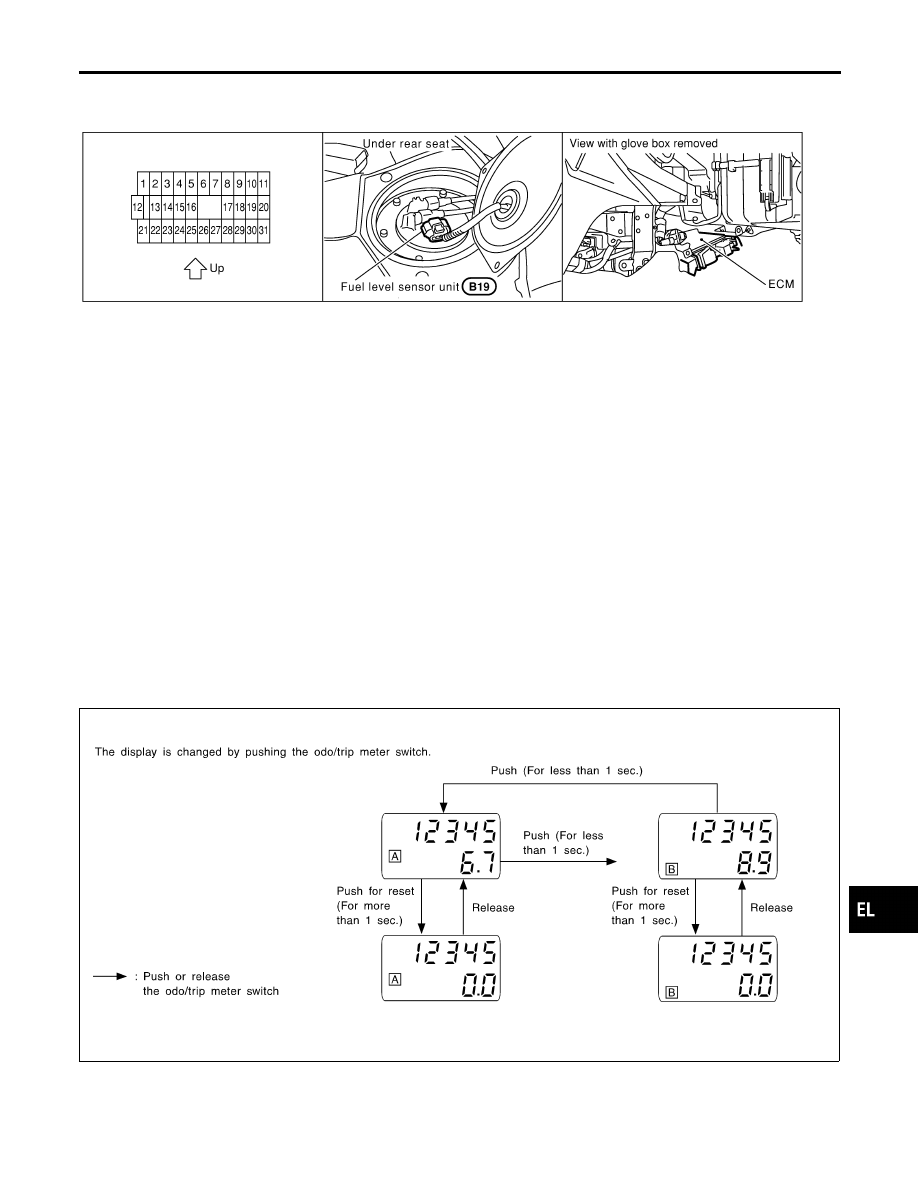
Location
NHEL0041
SEL550Y
System Description
NHEL0042
UNIFIED CONTROL METER
NHEL0042S06
I
Speedometer, odo/trip meter, tachometer, fuel gauge and water temperature gauge are controlled totally
by control unit built-in combination meter.
I
Digital meter is adopted for odo/trip meter.*
*The record of the odo meter is kept even if the battery cable is disconnected. The record of the trip meter
is erased when the battery cable is disconnected.
I
Odo/trip meter segment can be checked in diagnosis mode.
I
Meter/gauge can be checked in diagnosis mode.
HOW TO CHANGE THE DISPLAY FOR ODO/TRIP METER
NHEL0042S07
SEL175W
NOTE:
Turn ignition switch to the “ON” position to operate odo/trip meter.
GI
MA
EM
LC
EC
FE
AT
AX
SU
BR
ST
RS
BT
HA
SC
IDX
METERS AND GAUGES
Component Parts and Harness Connector Location
EL-125
POWER SUPPLY AND GROUND CIRCUIT
NHEL0042S08
Power is supplied at all times
I
through 10A fuse [No. 12, located in the fuse block (J/B)]
I
to combination meter terminal 62.
With the ignition switch in the ACC or ON position, power is supplied
I
through 10A fuse [No. 1, located in the fuse block (J/B)]
I
to combination meter terminal 31.
With the ignition switch in the ON or START position, power is supplied
I
through 10A fuse [No. 30, located in the fuse block (J/B)]
I
to combination meter terminal 66.
Ground is supplied
I
to combination meter terminal 59
I
through body grounds M9, M25 and M87.
WATER TEMPERATURE GAUGE
NHEL0042S01
The water temperature gauge indicates the engine coolant temperature. The reading on the gauge is received
engine coolant temperature signal from ECM. ECM is detected by water temperature sensor.
The water temperature gauge is received by a signal
I
from ECM terminal 18
I
to combination meter terminal 18
The needle on the gauge moves from “C” to “H”
TACHOMETER
NHEL0042S02
The tachometer indicates engine speed in revolutions per minute (rpm).
The tachometer is regulated by a signal
I
from terminal 34 of the ECM
I
to combination meter terminal 16 for the tachometer.
FUEL GAUGE
NHEL0042S03
The fuel gauge indicates the approximate fuel level in the fuel tank.
The fuel gauge is regulated by a variable ground signal supplied
I
to combination meter terminal 17 for the fuel gauge
I
from terminal 2 of the fuel level sensor unit
I
through terminal 5 of the fuel level sensor unit and
I
through body ground B7 (with TCS) or B78 (with VDC) and B46
SPEEDOMETER
NHEL0042S04
The combination meter provides a voltage signal to the vehicle speed sensor for the speedometer.
The voltage is supplied
I
from combination meter terminal 15 for the speedometer
I
to terminal 1 of the vehicle speed sensor (with VDC)
I
to terminal 22 of ABS/TCS control unit (with TCS)
The speedometer converts the voltage into the vehicle speed displayed.
METERS AND GAUGES
System Description (Cont’d)
EL-126
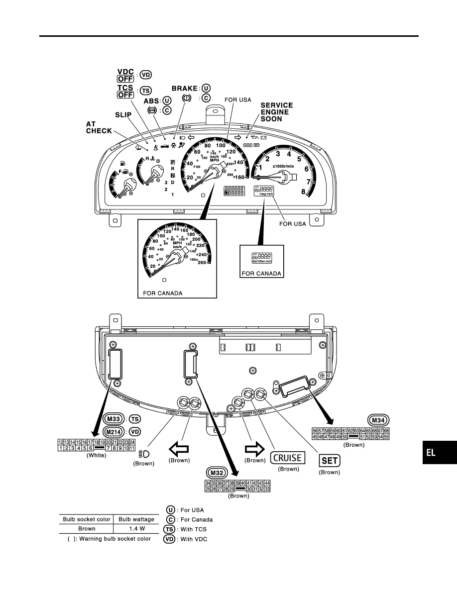
Combination Meter
NHEL0043
CHECK
NHEL0043S01
MEL875Q
GI
MA
EM
LC
EC
FE
AT
AX
SU
BR
ST
RS
BT
HA
SC
IDX
METERS AND GAUGES
Combination Meter
EL-127
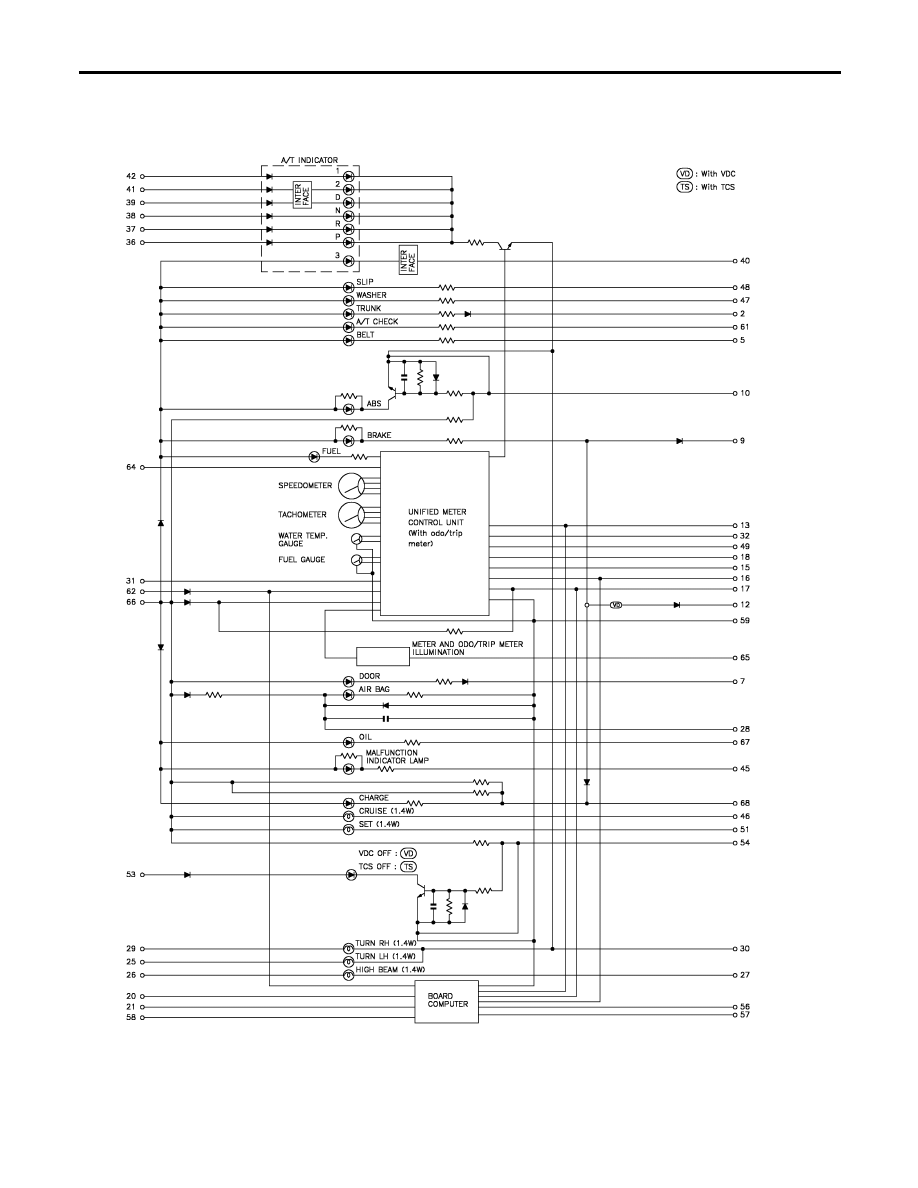
Schematic
NHEL0293
MEL700R
METERS AND GAUGES
Schematic
EL-128
Нет комментариевНе стесняйтесь поделиться с нами вашим ценным мнением.
Текст