Infiniti I35 (A33). Manual — part 484
SEM730G
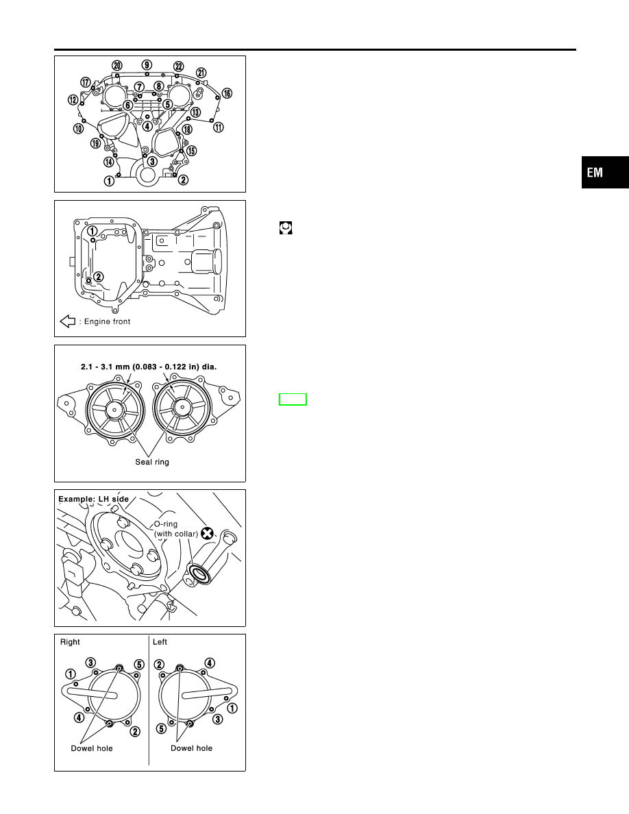
9.
Tighten bolts to the specified torque in order shown in the fig-
ure.
8 mm (0.31 in) dia. bolts: 1, 2
6 mm (0.24 in) dia. bolts: Except the above
I
After tightening, retighten them to specified torque in numeri-
cal order shown in figure.
SEM921G
10. Tighten two mounting bolts in front of oil pan (upper) in numeri-
cal order shown in figure.
: 15.7 - 18.6 N·m (1.6 - 1.9 kg-m, 12 - 13 ft-lb)
KBIA1314E
11. Install RH and LH intake valve timing control covers as follows:
a.
Install seal rings in shaft grooves.
b.
Apply liquid gasket to the intake valve timing control covers.
I
Use Genuine RTV Silicone Sealant or equivalent. Refer to
GI-53, “RECOMMENDED CHEMICAL PRODUCTSAND SEAL-
ANTS”.
SEM948G
c.
Install collared O-ring in front timing chain case oil hole (LH
and RH sides).
SEM728G
d.
Being careful not to move the seal ring from the installation
groove, align the dowel pins on the chain case with the holes
to install the intake valve timing control covers.
e.
Tighten bolts in the numerical order as shown.
GI
MA
LC
EC
FE
AT
AX
SU
BR
ST
RS
BT
HA
SC
EL
IDX
FRONT TIMING CHAIN CASE
Installation (Cont’d)
EM-27
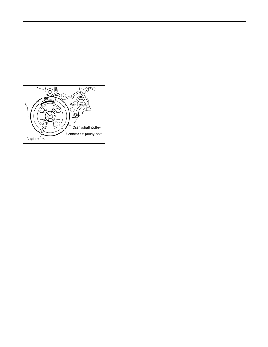
12. Install crankshaft pulley as follows:
a.
Fix crankshaft using a suitable tool.
b.
Install crankshaft pulley, taking care not to damage front oil
seal.
I
When press-fitting crankshaft pulley with a plastic hammer, tap
on its center portion (not circumference).
c.
Tighten bolt to 39.2 to 49.0 N·m (4.0 to 5.0 kg-m, 29 to 36 ft-
lb).
SEM751G
d.
Put a paint mark on crankshaft pulley aligning with angle mark
on crankshaft pulley bolt. Then, further retighten bolt by 60 to
66 degrees [Target: 60 degrees (equivalent to one gradua-
tion)].
13. Rotate crankshaft pulley in normal direction (clockwise when
viewed from front) to confirm it turns smoothly.
14. For the following operations, perform steps in the reverse order
of removal.
I
If hydraulic pressure inside chain tensioner drops after
removal/installation, slack in the guide may generate a pound-
ing noise during and just after engine start. However, this does
not indicate an unusualness. Noise will stop after hydraulic
pressure rises.
FRONT TIMING CHAIN CASE
Installation (Cont’d)
EM-28
Components
NHEM0011
SEM964G
GI
MA
LC
EC
FE
AT
AX
SU
BR
ST
RS
BT
HA
SC
EL
IDX
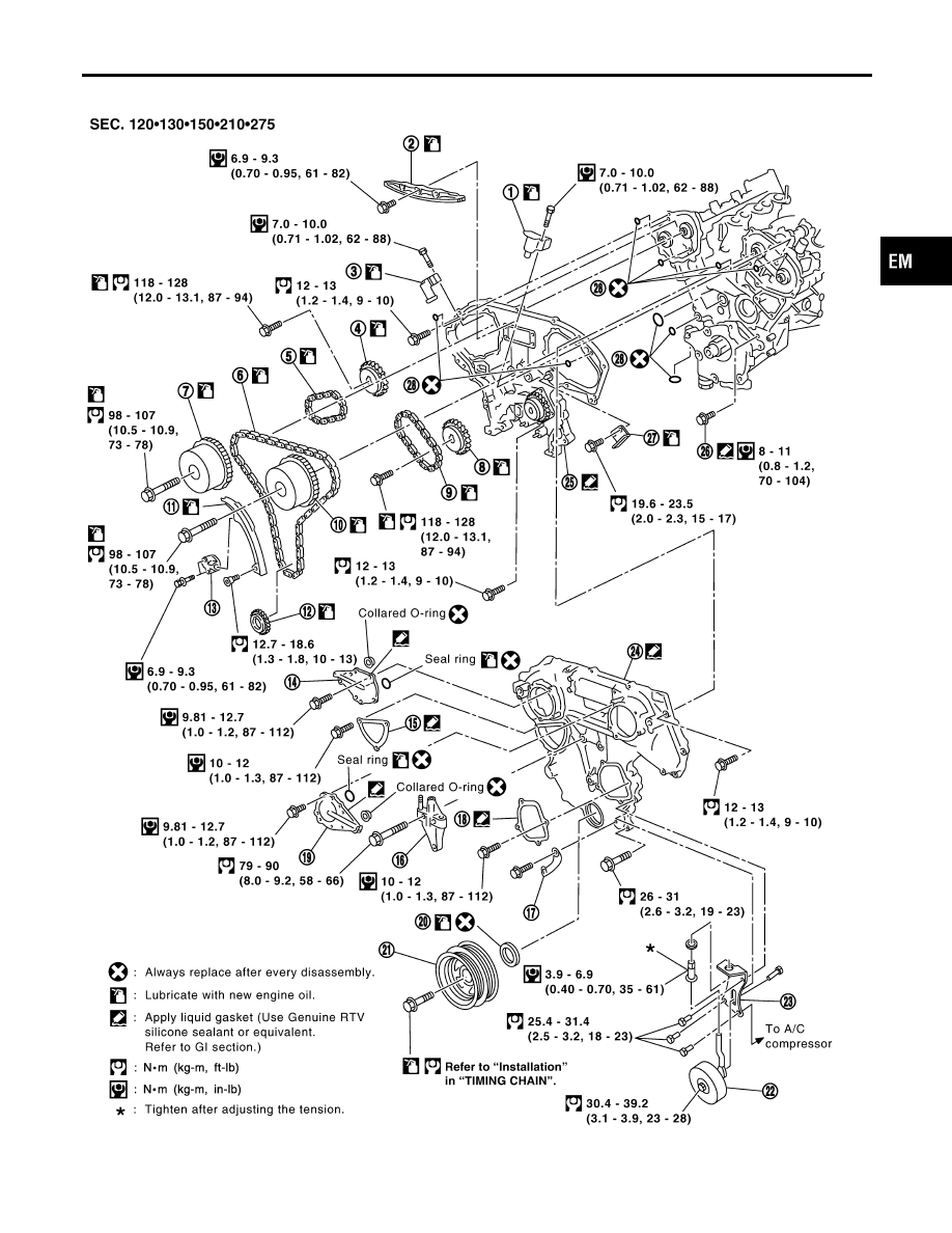
TIMING CHAIN
Components
EM-29
1.
Timing chain tensioner
2.
Internal chain guide
3.
Timing chain tensioner
4.
Camshaft sprocket (EXH)
5.
Timing chain (Secondary)
6.
Timing chain (Primary)
7.
Camshaft sprocket (INT)
8.
Camshaft sprocket (EXH)
9.
Timing chain (Secondary)
10. Camshaft sprocket (INT)
11. Slack guide
12. Crankshaft sprocket
13. Timing chain tensioner
14. Intake valve timing control cover
15. Chain tensioner cover
16. Mounting bracket
17. Water hose clamp
18. Water pump cover
19. Intake valve timing control cover
20. Front oil seal
21. Crankshaft pulley
22. Idler pulley
23. Idler pulley bracket
24. Front timing chain case
25. Rear timing chain case
26. Water drain plug
27. Tension guide
28. O-ring
TIMING CHAIN
Components (Cont’d)
EM-30
Нет комментариевНе стесняйтесь поделиться с нами вашим ценным мнением.
Текст