Infiniti I35 (A33). Manual — part 476
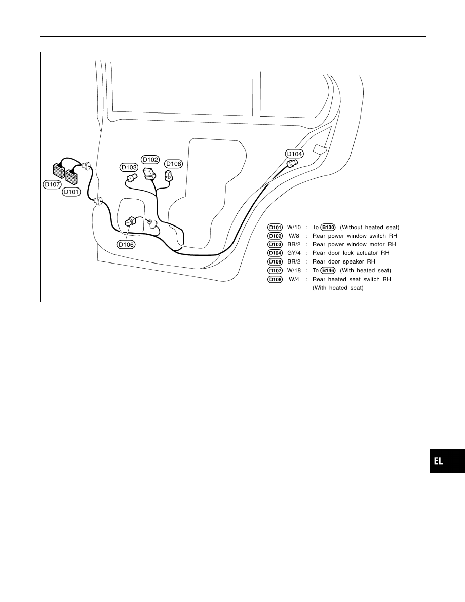
RH SIDE
NHEL0143S04
MEL696R
GI
MA
EM
LC
EC
FE
AT
AX
SU
BR
ST
RS
BT
HA
SC
IDX
HARNESS LAYOUT
Rear Door Harness (Cont’d)
EL-505

NHEL0144
Headlamp
NHEL0144S03
Item
Wattage (W)
High/Low
60/35 (HB3)
Exterior Lamp
NHEL0144S01
Item
Wattage (W)
Front fog lamp
21 (H3)
Front turn signal lamp
21
Parking lamp
5
Front side marker lamp
3.8
Rear combination lamp
Turn signal
21
Stop/Tail
21/5
Back-up
18
Rear side marker lamp
3.8
License lamp
5
High-mounted stop lamp
Without rear air spoiler
5
With rear air spoiler
LED
Interior Lamp
NHEL0144S02
Item
Wattage (W)
Interior room lamp
10
Spot lamp
8
Vanity mirror lamp
8
Trunk room lamp
3.4
Step lamp
2.7
BULB SPECIFICATIONS
Headlamp
EL-506

NHEL0145
Use the chart below to find out what each wiring
diagram code stands for.
Refer to the wiring diagram code in the alphabetical
index to find the location (page number) of each
wiring diagram.
Code
Section
Wiring Diagram Name
1STSIG
AT
A/T 1ST Signal
2NDSIG
AT
A/T 2ND Signal
3RDSIG
AT
A/T 3RD Signal
4THSIG
AT
A/T 4TH Signal
A/C, A
HA
Auto Air Conditioner
APPS2
EC
Accelerator Pedal Position Sen-
sor (Sensor 2)
APPS3
EC
Accelerator Pedal Position Sen-
sor
ASC/BS
EC
Automatic Speed Control Device
(ASCD) Brake Switch
ASC/SW
EC
Automatic Speed Control Device
(ASCD) Steering Switch
ASC/VS
EC
Automatic Speed Control Device
(ASCD) Vehicle Speed Sensor
ASCBOF
EC
Automatic Speed Control Device
(ASCD) Brake Switch (Off)
ASCIND
EC
Automatic Speed Control Device
(ASCD) Indicator
AT/IND
EL
A/T Indicator
AUDIO
EL
Audio
AUT/DP
EL
Automatic Drive Positioner
BACK/L
EL
Back-up Lamp
BA/FTS
AT
A/T Fluid Temperature Sensor
and TCM Power Supply
B/COMP
EL
Board Computer
BRK/SW
EC
Brake Switch
BYPS/V
EC
Vacuum Cut Valve Bypass Valve
CAN
AT
CAN Communication Line
CAN
EC
CAN Communication Line
CAN
EL
CAN System
CHARGE
SC
Charging System
CHIME
EL
Warning Chime
CIGAR
EL
Cigarette Lighter
CLOCK
EL
Clock
COMPAS
EL
Compass
COOL/F
EC
Cooling Fan Control
CORNER
EL
Cornering Lamp
Code
Section
Wiring Diagram Name
DEF
EL
Rear Window Defogger
D/LOCK
EL
Power Door Lock
DLC
EC
Data Link Connectors
DTRL
EL
Headlamp - With Daytime Light
System
ECM/PW
EC
ECM Power Supply
ECTS
EC
Engine Coolant Temperature
Sensor
EMNT
EC
Electronic Controlled Engine
Mount
ENGSS
AT
Engine Speed Signal
ETC1
EC
Electrical Throttle Control Func-
tion
ETC2
EC
Electrical Throttle Control Motor
Relay
ETC3
EC
Electrical Throttle Control Motor
F/FOG
EL
Front Fog Lamp
FLS1
EC
Fuel Level Sensor Circuit
(SLOSH)
FLS2
EC
Fuel Level Sensor Circuit
FLS3
EC
Fuel Level Sensor Circuit
(Ground Signal)
F/PUMP
EC
Fuel Pump Control
FTS
AT
A/T Fluid Temperature Sensor
FTTS
EC
Fuel Tank Temperature Sensor
FUELB1
EC
Fuel Injection System Function
(Bank 1)
FUELB2
EC
Fuel Injection System Function
(Bank 2)
H/LAMP
EL
Headlamp
HORN
EL
Horn
HSEAT
EL
Heated Seat
H/STRG
EL
Heated Steering
I/MIRR
EL
Inside Mirror (Auto Anti-dazzling
Mirror)
IATS
EC
Intake Air Temperature Sensor
IGNSYS
EC
Ignition Signal
ILL
EL
Illumination
INJECT
EC
Injector
INT/L
EL
Interior, Step, Spot, Vanity Mirror
and Trunk Room Lamps
IVCB1
EC
Intake Valve Timing Control Sole-
noid Valve (Bank 1)
GI
MA
EM
LC
EC
FE
AT
AX
SU
BR
ST
RS
BT
HA
SC
IDX
WIRING DIAGRAM CODES (CELL CODES)
EL-507

Code
Section
Wiring Diagram Name
IVCB2
EC
Intake Valve Timing Control Sole-
noid Valve (Bank 2)
KEYLES
EL
Remote Keyless Entry System
KS
EC
Knock Sensor
LOAD
EC
Electrical Load Signal
LPSV
AT
Line Pressure Solenoid Valve
MAFS
EC
Mass Air Flow Sensor
MAIN
AT
Main Power Supply and Ground
Circuit
MAIN
EC
Main Power Supply and Ground
Circuit
METER
EL
Speedometer, Tachometer,
Temp., and Fuel Gauges
MIL
EC
Malfunction Indicator Lamp
MIRROR
EL
Power Door Mirror
NATS
EL
IVIS (Infiniti Vehicle Immobilizer
System — NATS)
NAVI
EL
Navigation System
NONDTC
AT
Non-detectable Items
O2H1B1
EC
Heated Oxygen Sensor 1 Heater
(Bank 1)
O2H1B2
EC
Heated Oxygen Sensor 1 Heater
(Bank 2)
O2H2B1
EC
Heated Oxygen Sensor 2 Heater
(Bank 1)
O2H2B2
EC
Heated Oxygen Sensor 2 Heater
(Bank 2)
O2S1B1
EC
Heated Oxygen Sensor 1 (Bank
1)
O2S1B2
EC
Heated Oxygen Sensor 1 (Bank
2)
O2S2B1
EC
Heated Oxygen Sensor 2 (Bank
1)
O2S2B2
EC
Heated Oxygen Sensor 2 (Bank
2)
OVRCSV
AT
Overrun Clutch Solenoid Valve
PHASE
EC
Camshaft Position Sensor
(Phase) Bank 1
PHASE
EC
Camshaft Position Sensor
(Phase) Bank 2
PHONE
EL
Telephone (Pre-wire)
PGC/V
EC
EVAP Canister Purge Volume
Control Solenoid Valve
PNP/SW
AT
Park/Neutral Position Switch
Code
Section
Wiring Diagram Name
PNP/SW
EC
Park/Neutral Position Switch
POS
EC
Crankshaft Position Sensor
(CKPS) (POS)
POWER
EL
Power Supply Routing
PRE/SE
EC
EVAP Control System Pressure
Sensor
PS/SEN
EC
Power Steering Pressure Sensor
PT/SEN
AT
Power Train Revolution Sensor
REMOTE
EL
Audio (Remote Control Switch)
RP/SEN
EC
Refrigerant Pressure Sensor
SEAT
EL
Power Seat
SEN/PW
EC
Sensor Power Supply
SHADE
EL
Rear Sunshade
SHIFT
AT
A/T Shift Lock System
SROOF
EL
Sunroof
SRS
RS
Supplemental Restraint System
S/SIG
EC
Start Signal
SSV/A
AT
Shift Solenoid Valve A
SSV/B
AT
Shift Solenoid Valve B
START
SC
Starting System
STOP/L
EL
Stop Lamp
TAIL/L
EL
Parking, License and Tail Lamps
TCCSIG
AT
A/T TCC Signal (Lock Up)
TCS
BR
Traction Control System
TCV
AT
Torque Converter Clutch Solenoid
Valve
T&FLID
EL
Trunk Lid and Fuel Filler Lid
Opener
TPS
AT
Throttle Position Sensor
TPS1
EC
Throttle Position Sensor (Sensor
1)
TPS2
EC
Throttle Position Sensor (Sensor
2)
TPS3
EC
Throttle Position Sensor
TRNSCV
EL
Homelink Universal Transceiver
TURN
EL
Turn Signal and Hazard Warning
Lamps
VDC
BR
Vehicle Dynamics Control
VEHSEC
EL
Vehicle Security (Theft Warning)
System
VENT/V
EC
EVAP Canister Vent Control
Valve
WIRING DIAGRAM CODES (CELL CODES)
EL-508
Нет комментариевНе стесняйтесь поделиться с нами вашим ценным мнением.
Текст