Infiniti I35 (A33). Manual — part 56
MAT491B
GI
MA
EM
LC
EC
FE
AX
SU
BR
ST
RS
BT
HA
SC
EL
IDX
TROUBLE DIAGNOSES FOR SYMPTOMS
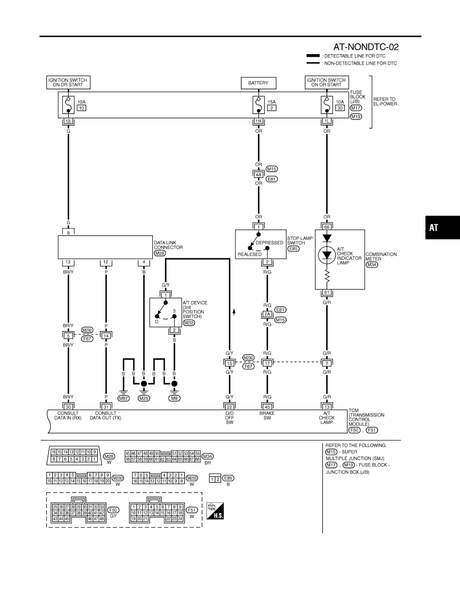
Wiring Diagram — AT — NONDTC (Cont’d)
AT-221
A/T CHECK Indicator Lamp Does Not Come On
NHAT0088
SYMPTOM:
A/T CHECK indicator lamp does not come on for about 2 sec-
onds when turning ignition switch to ON.
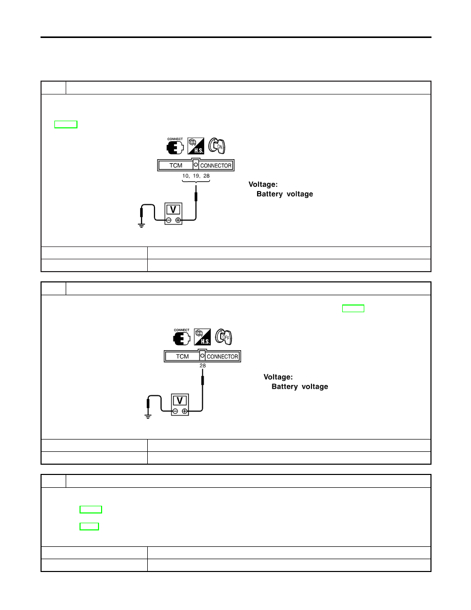
1
CHECK TCM POWER SOURCE
1. Turn ignition switch to ON position.
(Do not start engine.)
2. Check voltage between TCM harness connectors F50, F51 terminals 10 (R/Y), 19 (R/Y), 28 (Y/R) and ground. Refer to
AT-101, “Wiring Diagram —AT— MAIN”.
SAT611J
OK or NG
OK
©
GO TO 2.
NG
©
GO TO 3.
2
CHECK POWER SOURCE STEP 2
1. Turn ignition switch to OFF position.
2. Check voltage between TCM harness connector F50 terminal 28 (Y/R) and ground. Refer to AT-101, “Wiring Diagram
—AT— MAIN”.
SAT612JG
OK or NG
OK
©
GO TO 4.
NG
©
GO TO 3.
3
DETECT MALFUNCTIONING ITEM
Check the following items:
I
Harness for short or open between battery, ignition switch and TCM
Refer to AT-101, “Wiring Diagram — AT — MAIN”.
I
Ignition switch and fuse
Refer to EL-11, “POWER SUPPLY ROUTING”.
OK or NG
OK
©
GO TO 4.
NG
©
Repair or replace damaged parts.
TROUBLE DIAGNOSES FOR SYMPTOMS
A/T CHECK Indicator Lamp Does Not Come On
AT-222
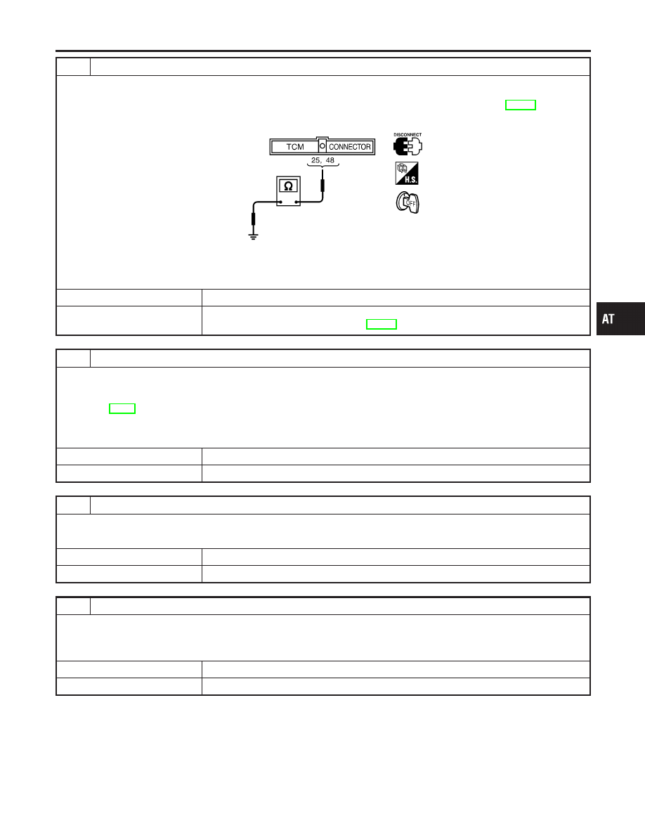
4
CHECK TCM GROUND CIRCUIT
1. Turn ignition switch to OFF position.
2. Disconnect TCM harness connector.
3. Check continuity between TCM harness connector F50 terminals 25 (B), 48 (B) and ground. Refer to AT-101, “Wiring
Diagram — AT — MAIN”.
SAT515J
Continuity should exist.
If OK, check harness for short to ground and short to power.
OK or NG
OK
©
GO TO 5.
NG
©
Repair open circuit or short to ground or short to power in harness or connectors. Refer
to “Wiring Diagram — AT — MAIN” in AT-101.
5
DETECT MALFUNCTIONING ITEM
Check the following items:
I
A/T CHECK indicator lamp
I
Harness and fuse for short or open between ignition switch and combination meter
Refer to EL-11, “POWER SUPPLY ROUTING”.
I
Harness for short or open between combination meter and TCM
OK or NG
OK
©
GO TO 6.
NG
©
Repair or replace damaged parts.
6
CHECK SYMPTOM
Check again.
OK or NG
OK
©
INSPECTION END
NG
©
GO TO 7.
7
CHECK TCM INSPECTION
1. Perform TCM input/output signal inspection.
2. If NG, recheck TCM pin terminals for damage or loose connection with harness connector.
OK or NG
OK
©
INSPECTION END
NG
©
Repair or replace damaged parts.
GI
MA
EM
LC
EC
FE
AX
SU
BR
ST
RS
BT
HA
SC
EL
IDX
TROUBLE DIAGNOSES FOR SYMPTOMS
A/T CHECK Indicator Lamp Does Not Come On (Cont’d)
AT-223
Engine Cannot Be Started In P and N Position
=NHAT0089
SYMPTOM:
I
Engine cannot be started with selector lever in P or N
position.
I
Engine can be started with selector lever in D, 2, 1 or R
position.
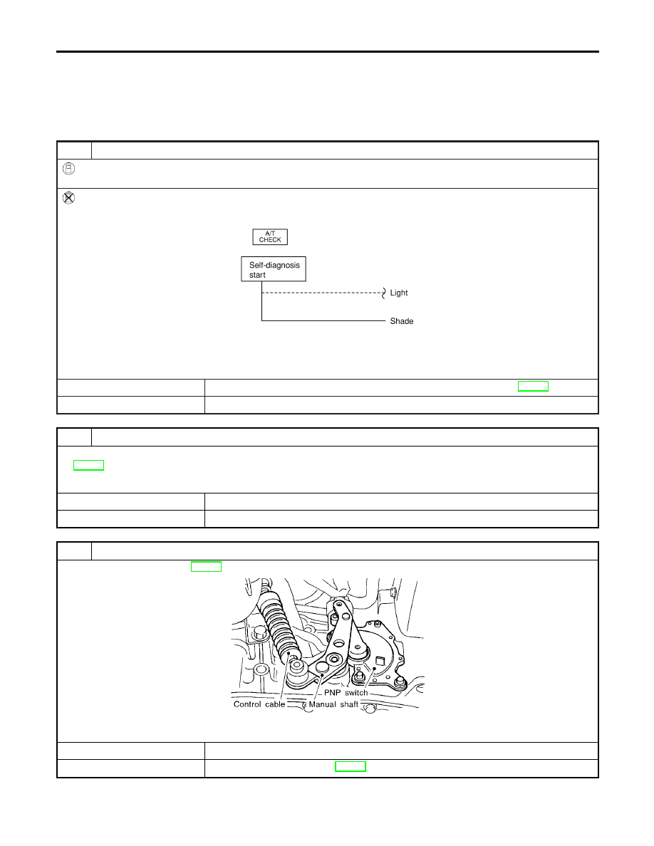
1
CHECK PARK/NEUTRAL POSITION (PNP) SWITCH CIRCUIT
With CONSULT-II
Does “TCM INPUT SIGNALS” in “DATA MONITOR” show damage to park/neutral position (PNP) switch circuit?
Without CONSULT-II
Does self-diagnosis show damage to park/neutral position (PNP) switch circuit?
SAT555K
Yes or No
Yes
©
Check park/neutral position (PNP) switch circuit. Refer to “DTC P0705”, AT-108.
No
©
GO TO 2.
2
CHECK PARK/NEUTRAL POSITION (PNP) SWITCH
Check for short or open of park/neutral position (PNP) switch harness connector F94 terminals 1 (G/OR) and 2 (B). Refer
to AT-110.
OK or NG
OK
©
GO TO 3.
NG
©
Repair or replace park/neutral position (PNP) switch.
3
ADJUST CONTROL CABLE
Check control cable. Refer to AT-284.
SAT023JA
OK or NG
OK
©
GO TO 4.
NG
©
Adjust control cable. Refer to AT-284.
TROUBLE DIAGNOSES FOR SYMPTOMS
Engine Cannot Be Started In P and N Position
AT-224
Нет комментариевНе стесняйтесь поделиться с нами вашим ценным мнением.
Текст