Infiniti I35 (A33). Manual — part 178
hose connection in the reverse direction.
On vehicles with an excessively high blow-by, the valve does not
meet the requirement. This is because some of the flow will go
through the hose connection to the air inlet tubes under all
conditions.
SEC137A
INSPECTION
NHEC0022
PCV (Positive Crankcase Ventilation) Valve
NHEC0022S01
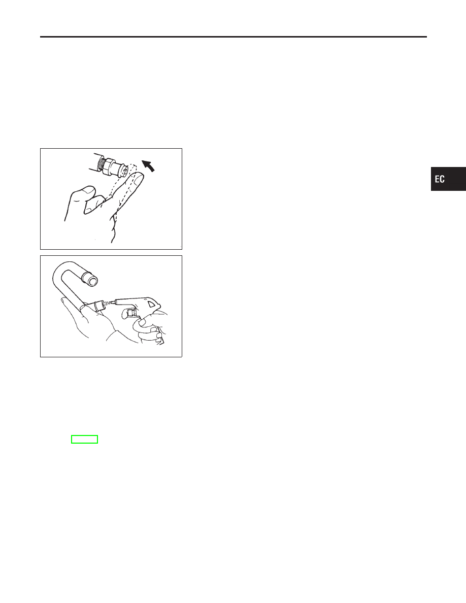
With engine running at idle, remove PCV valve from rocker cover.
A properly working valve makes a hissing noise as air passes
through it. A strong vacuum should be felt immediately when a fin-
ger is placed over valve inlet.
ET277
PCV Valve Ventilation Hose
NHEC0022S02
1.
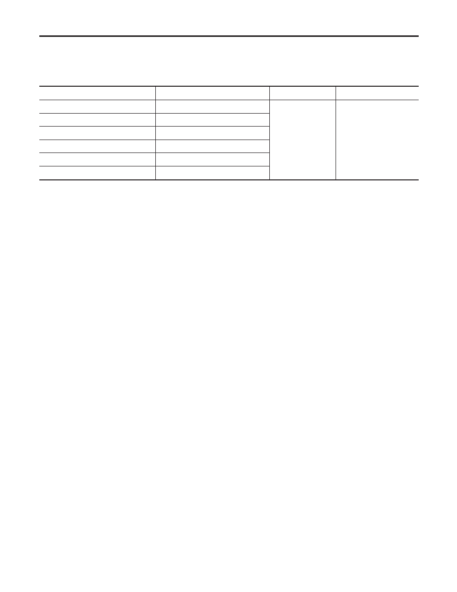
Check hoses and hose connections for leaks.
2.
Disconnect all hoses and clean with compressed air. If any
hose cannot be freed of obstructions, replace.
CAN Communication
NHEC1183
SYSTEM DESCRIPTION
NHEC1183S01
CAN (Controller Area Network) is a serial communication line for real time application. It is an on-vehicle mul-
tiplex communication line with high data communication speed and excellent error detection ability. Many
electronic control units are equipped onto a vehicle, and each control unit shares information and links with
other control units during operation (not independent). In CAN communication, control units are connected with
2 communication lines (CAN H line, CAN L line) allowing a high rate of information transmission with less wir-
ing. Each control unit transmits/receives data but selectively reads required data only.
Refer to EL-448, “CAN COMMUNICATION” for details of CAN communication.
GI
MA
EM
LC
FE
AT
AX
SU
BR
ST
RS
BT
HA
SC
EL
IDX
ENGINE AND EMISSION BASIC CONTROL SYSTEM DESCRIPTION
Positive Crankcase Ventilation (Cont’d)
EC-53
Automatic Speed Control Device (ASCD)
System
DESCRIPTION
=NHEC1184
Input/Output Signal Chart
NHEC1184S01
Sensor
Input signal to ECM
ECM function
Actuator
ASCD brake switch
Brake pedal operation
ASCD vehicle speed
control
Electric throttle control
actuator
Stop lamp switch
Brake pedal operation
ASCD steering switch
ASCD steering switch operation
Park/Neutral position (PNP) switch
Gear position
Combination meter
Vehicle speed
TCM
Power train revolution
Basic ASCD System
NHEC1184S02
Refer to Owner’s Manual for ASCD operating instructions.
Automatic Speed Control Device (ASCD) allows a driver to keep vehicle at predetermined constant speed
without depressing accelerator pedal. Driver can set vehicle speed in advance between approximately 40 km/h
(25 MPH) and 144 km/h (89 MPH).
ECM controls throttle valve operating angle of electric throttle control actuator to regulate engine speed.
Operation status of ASCD is indicated by CRUISE indicator and SET indicator in combination meter.
If any malfunction occurs in ASCD system, it automatically deactivates control.
Set Operation
NHEC1184S03
Press ASCD CRUISE switch (Main switch). (Then CRUISE indicator in combination meter illuminates.)
When vehicle speed reaches a desired speed between approximately 40 km/h (25 MPH) and 144 km/h (89
MPH), press SET switch. (Then SET indicator in combination meter illuminates.)
Accel Operation
NHEC1184S04
If the RESUME/ACCEL switch is depressed during cruise control driving, increase the vehicle speed until the
switch is released or vehicle speed reaches maximum speed controlled by the system.
And then ASCD will keep the new set speed.
Cancel Operation
NHEC1184S05
When any of following conditions exist, cruise operation will be canceled.
I
CANCEL switch is depressed.
I
More than 2 switches at ASCD steering switch are depressed at the same time (Set speed will be cleared.).
I
Brake pedal is depressed.
I
A/T selector lever is shifted to P, N or R position.
I
Vehicle speed decreased to 13 km/h (8 MPH) lower than the set speed
I
TCS system is operated
If MAIN switch is turned to OFF while ASCD is activated, all of ASCD operations will be canceled and vehicle
speed memory will be erased.
Coast Operation
NHEC1184S06
When the SET/COAST switch is depressed during cruise control driving, decrease vehicle set speed until the
switch is released. And then ASCD will keep the new set speed.
Resume Operation
NHEC1184S07
When the RESUME/ACCEL switch is depressed after cancel operation other than depressing MAIN switch is
performed, vehicle speed will return to last set speed. To resume vehicle set speed, vehicle condition must
meet following conditions.
I
Brake pedal is released.
I
A/T selector lever is in other than P, N and R positions.
I
Vehicle speed is greater than 40 km/h (25 MPH) and 144 km/h (89 MPH).
ENGINE AND EMISSION BASIC CONTROL SYSTEM DESCRIPTION
Automatic Speed Control Device (ASCD) System
EC-54
SEF289X
SEF214Y
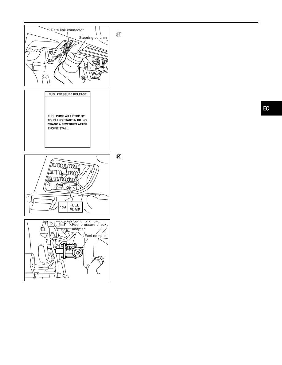
Fuel Pressure Release
NHEC0023
WITH CONSULT-II
NHEC0023S01
1.
Turn ignition switch ON.
2.
Perform “FUEL PRESSURE RELEASE” in “WORK SUP-
PORT” mode with CONSULT-II.
3.
Start engine.
4.
After engine stalls, crank it two or three times to release all fuel
pressure.
5.
Turn ignition switch OFF.
SEF997Z
WITHOUT CONSULT-II
NHEC0023S02
1.
Remove fuel pump fuse located in fuse box.
2.
Start engine.
3.
After engine stalls, crank it two or three times to release all fuel
pressure.
4.
Turn ignition switch OFF.
5.
Reinstall fuel pump fuse after servicing fuel system.
SEC997C
Fuel Pressure Check
NHEC0024
Before disconnecting fuel line, release fuel pressure from fuel
line to eliminate danger.
NOTE:
Prepare pans and saucers under the disconnected fuel line
bacause the fuel may spill out. The fuel pressure cannot be com-
pletely released because I35 models do not have fuel return sys-
tem.
I
Use Pressure Gauge kit (J44321) to check fuel pressure.
1.
Release fuel pressure to zero.
2.
Disconnect fuel tube joint between fuel damper and injector
tube and set fuel pressure check adapter (J44321).
GI
MA
EM
LC
FE
AT
AX
SU
BR
ST
RS
BT
HA
SC
EL
IDX
BASIC SERVICE PROCEDURE
Fuel Pressure Release
EC-55
SEC998C
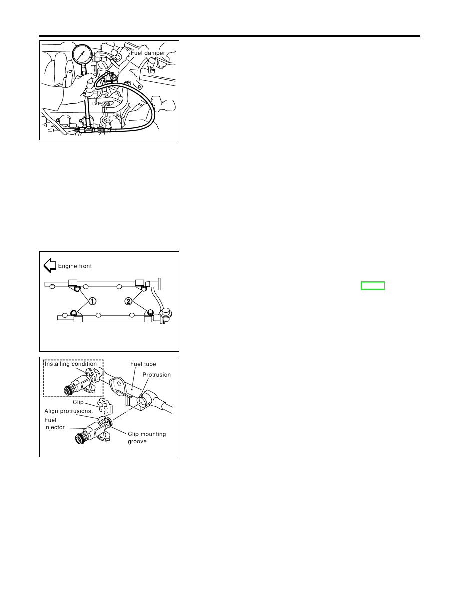
3.
Install pressure gauge to the fuel pressure check adapter as
shown in the figure.
4.
Start engine and check for fuel leakage.
5.
Read the indication of fuel pressure gauge.
At idling: Approximately 350 kPa (3.57 kg/cm
2
, 51 psi)
6.
If results are unsatisfactory, go to next step.
7.
Check the following.
I
Fuel hoses and fuel tubes for clogging
I
Fuel filter for clogging
I
Fuel pump
I
Fuel pressure regulator for clogging
If OK, replace fuel pressure regulator.
If NG, repair or replace.
SEC030D
SEF703X
Injector
REMOVAL AND INSTALLATION
NHEC0026
1.
Release fuel pressure to zero.
2.
Remove intake manifold collector. Refer to EM-29, “TIMING
CHAIN”.
3.
Remove fuel tube assemblies in numerical sequence as
shown in the figure at left.
4.
Expand and remove clips securing fuel injectors.
5.
Extract fuel injectors straight from fuel tubes.
I
Be careful not to damage injector nozzles during removal.
I
Do not bump or drop fuel injectors.
6.
Carefully install O-rings.
I
Lubricate O-rings with a smear of engine oil.
I
Be careful not to damage O-rings with service tools, fin-
ger nails or clips. Do not expand or twist O-rings.
I
Discard old clips; replace with new ones.
7.
Position clips in grooves on fuel injectors.
I
Make sure that protrusions of fuel injectors are aligned
with cutouts of clips after installation.
BASIC SERVICE PROCEDURE
Fuel Pressure Check (Cont’d)
EC-56
Нет комментариевНе стесняйтесь поделиться с нами вашим ценным мнением.
Текст