Infiniti I35 (A33). Manual — part 510
NHGI0003
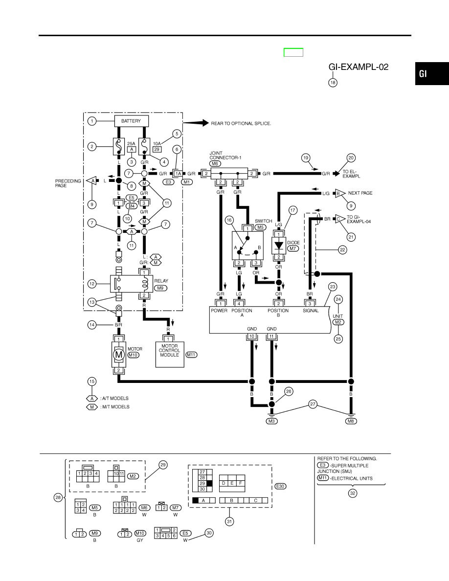
Sample/Wiring Diagram — EXAMPL —
NHGI0003S01
I
For Description, refer to GI-14.
SGI091A
MA
EM
LC
EC
FE
AT
AX
SU
BR
ST
RS
BT
HA
SC
EL
IDX
HOW TO READ WIRING DIAGRAMS
Sample/Wiring Diagram — EXAMPL —
GI-11
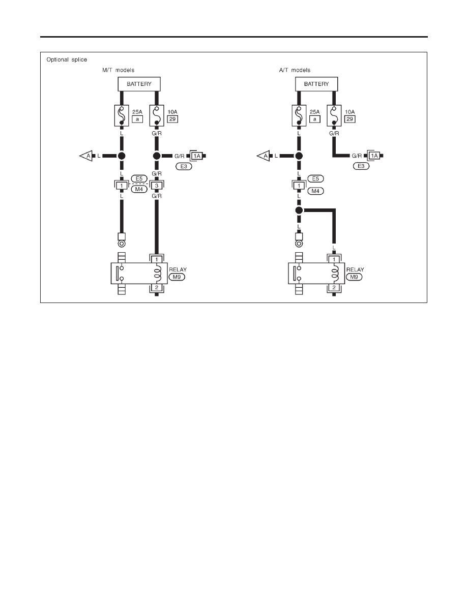
OPTIONAL SPLICE
NHGI0003S0101
SGI942
HOW TO READ WIRING DIAGRAMS
Sample/Wiring Diagram — EXAMPL — (Cont’d)
GI-12
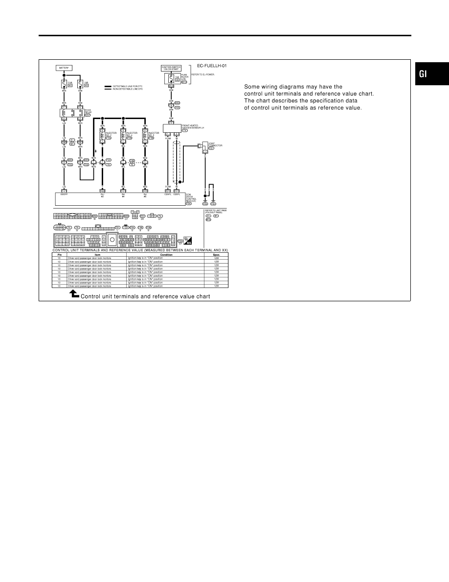
CONTROL UNIT TERMINALS AND REFERENCE VALUE
CHART
NHGI0003S0102
SGI095A
MA
EM
LC
EC
FE
AT
AX
SU
BR
ST
RS
BT
HA
SC
EL
IDX
HOW TO READ WIRING DIAGRAMS
Sample/Wiring Diagram — EXAMPL — (Cont’d)
GI-13

Description
=NHGI0003S02
Number
Item
Description
1
Power condition
I
This shows the condition when the system receives battery positive voltage (can be
operated).
2
Fusible link
I
The double line shows that this is a fusible link.
I
The open circle shows current flow in, and the shaded circle shows current flow out.
3
Fusible link/fuse loca-
tion
I
This shows the location of the fusible link or fuse in the fusible link or fuse box. For
arrangement, refer to EL-12, “POWER SUPPLY ROUTING”.
4
Fuse
I
The single line shows that this is a fuse.
I
The open circle shows current flow in, and the shaded circle shows current flow out.
5
Current rating
I
This shows the current rating of the fusible link or fuse.
6
Connectors
I
This shows that connector E3 is female and connector M1 is male.
I
The G/R wire is located in the 1A terminal of both connectors.
I
Terminal number with an alphabet (1A, 5B, etc.) indicates that the connector is SMJ con-
nector. Refer to GI-19.
7
Optional splice
I
The open circle shows that the splice is optional depending on vehicle application.
8
Splice
I
The shaded circle shows that the splice is always on the vehicle.
9
Page crossing
I
This arrow shows that the circuit continues to an adjacent page.
I
The A will match with the A on the preceding or next page.
10
Common connector
I
The dotted lines between terminals show that these terminals are part of the same con-
nector.
11
Option abbreviation
I
This shows that the circuit is optional depending on vehicle application.
12
Relay
I
This shows an internal representation of the relay. For details, refer to EL-9, “STAN-
DARDIZED RELAY”.
13
Connectors
I
This shows that the connector is connected to the body or a terminal with bolt or nut.
14
Wire color
I
This shows a code for the color of the wire.
B = Black
W = White
R = Red
G = Green
L = Blue
Y = Yellow
LG = Light Green
BR = Brown
OR = Orange
P = Pink
PU = Purple
GY = Gray
SB = Sky Blue
CH = Dark Brown
DG = Dark Green
When the wire color is striped, the base color is given first, followed by the stripe color as
shown below:
Example: L/W = Blue with White Stripe
15
Option description
I
This shows a description of the option abbreviation used on the page.
16
Switch
I
This shows that continuity exists between terminals 1 and 2 when the switch is in the A
position. Continuity exists between terminals 1 and 3 when the switch is in the B posi-
tion.
17
Assembly parts
I
Connector terminal in component shows that it is a harness incorporated assembly.
18
Cell code
I
This identifies each page of the wiring diagram by section, system and wiring diagram
page number.
19
Current flow arrow
I
Arrow indicates electric current flow, especially where the direction of standard flow (ver-
tically downward or horizontally from left to right) is difficult to follow.
I
A double arrow “
” shows that current can flow in either direction depending on cir-
cuit operation.
HOW TO READ WIRING DIAGRAMS
Description
GI-14
Нет комментариевНе стесняйтесь поделиться с нами вашим ценным мнением.
Текст