Infiniti I35 (A33). Manual — part 204
6
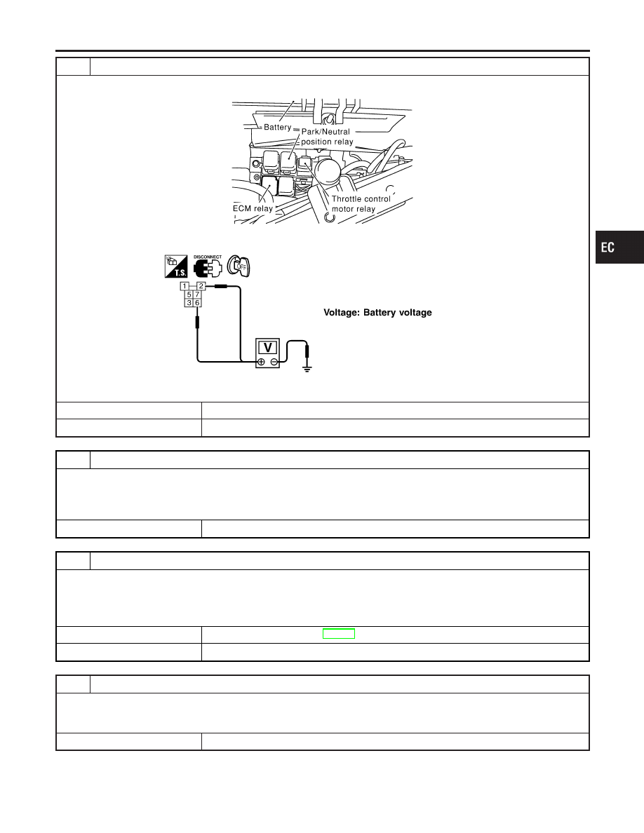
CHECK POWER SUPPLY-II
1. Disconnect ECM relay.
SEC044D
2. Check voltage between ECM relay terminals 2, 6 and ground with CONSULT-II or tester.
SEF292X
OK or NG
OK
©
GO TO 8.
NG
©
GO TO 7.
7
DETECT MALFUNCTIONING PART
Check the following.
I
15A fuses
I
Joint connector-13
I
Harness for open or short between ECM relay and battery
©
Repair open circuit or short to ground or short to power in harness or connectors.
8
CHECK OUTPUT SIGNAL CIRCUIT FOR OPEN AND SHORT
1. Check harness continuity between ECM terminal 38 and ECM relay terminal 1. Refer to WIRING DIAGRAM.
Continuity should exist.
2. Also check harness for short to ground and short to power.
OK or NG
OK
©
Go to “IGNITION SIGNAL”, EC-685.
NG
©
GO TO 9.
9
DETECT MALFUNCTIONING PART
Check the following.
I
Harness connectors E15, F18
I
Harness for open or short between ECM relay and ECM
©
Repair open circuit or short to ground or short to power in harness or connectors.
GI
MA
EM
LC
FE
AT
AX
SU
BR
ST
RS
BT
HA
SC
EL
IDX
POWER SUPPLY AND GROUND CIRCUIT
Diagnostic Procedure (Cont’d)
EC-157
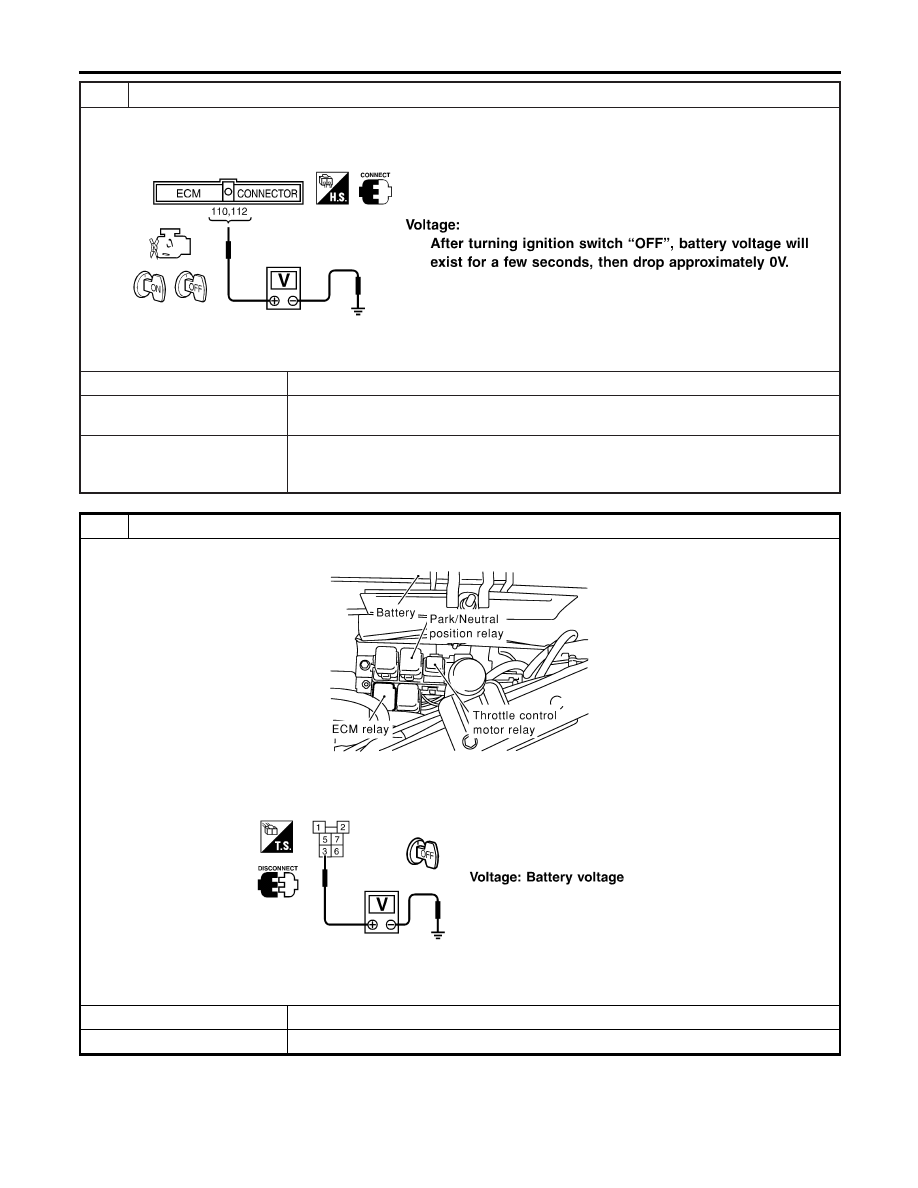
10
CHECK ECM POWER SUPPLY CIRCUIT-II
1. Turn ignition switch ON and then OFF.
2. Check voltage between ECM terminals 110, 112 and ground with CONSULT-II or tester.
SEF294X
OK or NG
OK
©
GO TO 16.
NG (Battery voltage
does not exist.)
©
GO TO 11.
NG (Battery voltage
exists for more than a
few seconds.)
©
GO TO 13.
11
CHECK ECM POWER SUPPLY CIRCUIT-III
1. Disconnect ECM relay.
SEC044D
2. Check voltage between ECM relay terminal 3 and ground with CONSULT-II or tester.
SEF295X
OK or NG
OK
©
GO TO 13.
NG
©
GO TO 12.
POWER SUPPLY AND GROUND CIRCUIT
Diagnostic Procedure (Cont’d)
EC-158
12
DETECT MALFUNCTIONING PART
Check the following.
I
Joint connector-13
I
Harness for open or short between ECM relay and 15A fuse
©
Repair open circuit or short to ground or short to power in harness or connectors.
13
CHECK HARNESS CONTINUITY BETWEEN ECM RELAY AND ECM FOR OPEN AND SHORT
1. Check harness continuity between ECM terminals 110, 112 and ECM relay terminal 5.
Refer to WIRING DIAGRAM.
Continuity should exist.
2. Also check harness for short to ground and short to power.
OK or NG
OK
©
GO TO 15.
NG
©
GO TO 14.
14
DETECT MALFUNCTIONING PART
Check the following.
I
Harness connectors E15, F18
I
Harness for open or short between ECM and ECM relay
©
Repair open circuit or short to ground or short to power in harness or connectors.
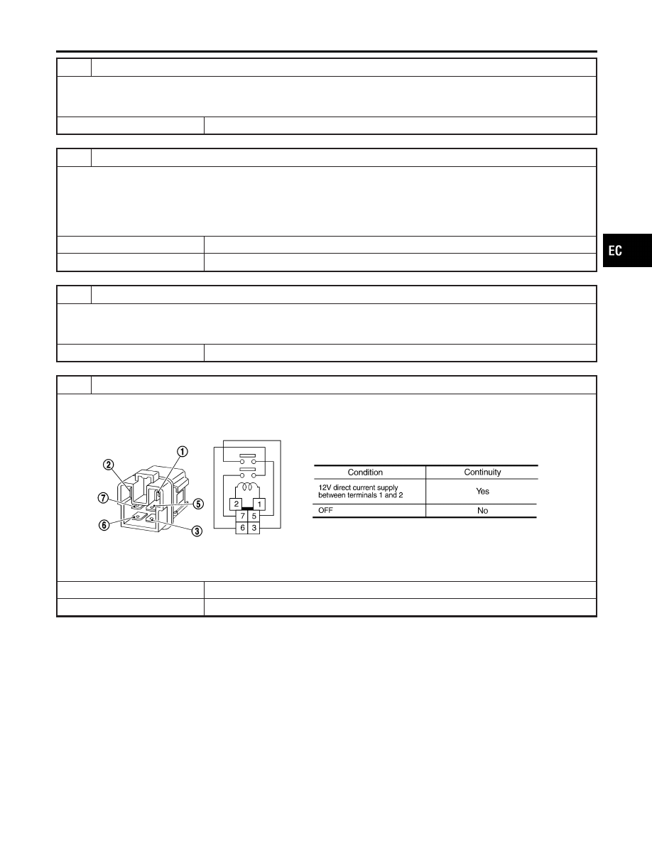
15
CHECK ECM RELAY
1. Apply 12V direct current between ECM relay terminals 1 and 2.
2. Check continuity between relay terminals 3 and 5, 6 and 7.
SEF296X
OK or NG
OK
©
GO TO 16.
NG
©
Replace ECM relay.
GI
MA
EM
LC
FE
AT
AX
SU
BR
ST
RS
BT
HA
SC
EL
IDX
POWER SUPPLY AND GROUND CIRCUIT
Diagnostic Procedure (Cont’d)
EC-159
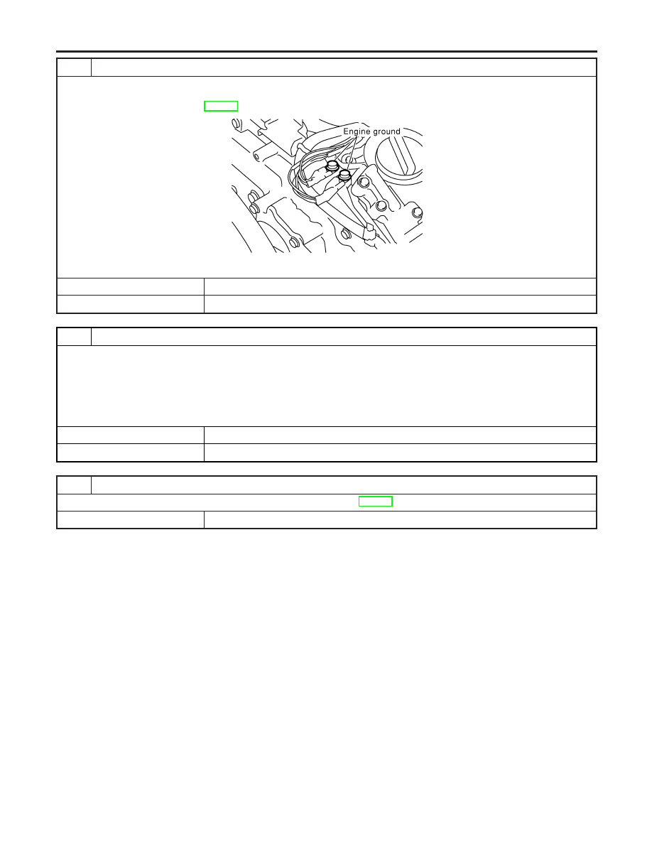
16
CHECK GROUND CONNECTIONS
1. Turn ignition switch OFF.
2. Loosen and retighten two engine ground screws.
Refer to “Ground Inspection”, EC-160.
SEC047D
OK or NG
OK
©
GO TO 17.
NG
©
Repair or replace ground connections.
17
CHECK ECM GROUND CIRCUIT FOR OPEN AND SHORT-II
1. Disconnect ECM harness connector.
2. Check harness continuity between ECM terminals 48, 57, 106, 108 and ground.
Refer to WIRING DIAGRAM.
Continuity should exist.
3. Also check harness for short to ground and short to power.
OK or NG
OK
©
GO TO 18.
NG
©
Repair open circuit or short to ground or short to power in harness or connectors.
18
CHECK INTERMITTENT INCIDENT
Refer to “TROUBLE DIAGNOSIS FOR INTERMITTENT INCIDENT”, EC-152.
©
INSPECTION END
Ground Inspection
NHEC1529
Ground connections are very important to the proper operation of
electrical and electronic circuits. Ground connections are often
exposed to moisture, dirt and other corrosive elements. The corro-
sion (rust) can become an unwanted resistance. This unwanted
resistance can change the way a circuit works.
Electronically controlled circuits are very sensitive to proper
grounding. A loose or corroded ground can drastically affect an
POWER SUPPLY AND GROUND CIRCUIT
Diagnostic Procedure (Cont’d)
EC-160
Нет комментариевНе стесняйтесь поделиться с нами вашим ценным мнением.
Текст