Infiniti I35 (A33). Manual — part 123
4. ABS Does Not Work
NHBR0191
1
CHECK WARNING LAMP INDICATION
Does the ABS warning lamp activate?
Yes
©
Carry out self-diagnosis. Refer to BR-46.
No
©
Go to “3. CHECK WARNING LAMP INDICATION” in “2. Unexpected Pedal Action”,
BR-75.
NOTE:
ABS does not work when vehicle speed is under 10 km/h (6 MPH).
GI
MA
EM
LC
EC
FE
AT
AX
SU
ST
RS
BT
HA
SC
EL
IDX
TROUBLE DIAGNOSES FOR SYMPTOMS
TCS
4. ABS Does Not Work
BR-77
5. Pedal Vibration and Noise
=NHBR0192
1
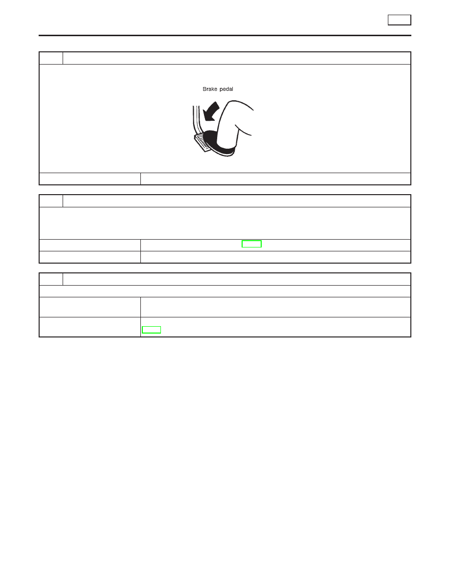
INSPECTION START
Pedal vibration and noise inspection
SAT797A
©
GO TO 2.
2
CHECK SYMPTOM
1. Apply brake.
2. Start engine.
Does the symptom appear only when engine is started?
Yes
©
Carry out self-diagnosis. Refer to BR-46.
No
©
GO TO 3.
3
RECHECK SYMPTOM
Does the symptom appear when electrical equipment switches (such as headlamp) are operated?
Yes
©
Check control unit pin for damage or the connection of control unit harness connector.
Then reconfirm the continuity.
No
©
Go to “3. CHECK WARNING LAMP INDICATION” in “2. Unexpected Pedal Action”,
BR-75.
NOTE:
ABS may operate and cause vibration under any of the following
conditions.
I
Applying brake gradually when shifting or operating clutch.
I
Low friction (slippery) road.
I
High speed cornering.
I
Driving over bumps and pot holes.
I
Engine speed is over 5,000 rpm with vehicle stopped.
TROUBLE DIAGNOSES FOR SYMPTOMS
TCS
5. Pedal Vibration and Noise
BR-78
6. ABS Warning Lamp Does Not Come On
When Ignition Switch Is Turned On
=NHBR0193
1
INSPECTION START
Warning lamp circuit inspection
SBR168F
©
GO TO 2.
2
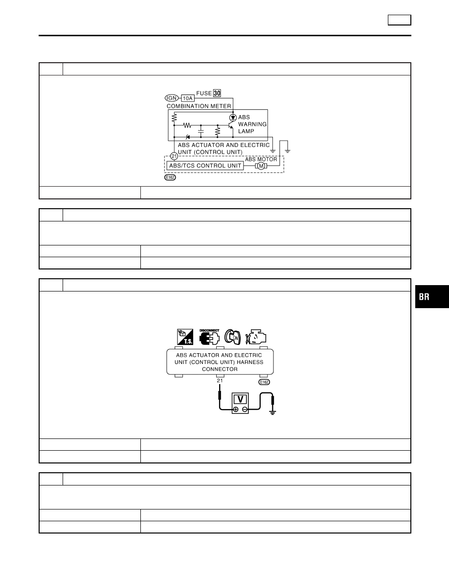
CHECK FUSE
Check 10A fuse No. 30 for warning lamp. For fuse layout, refer to “POWER SUPPLY ROUTING” in EL section.
Is fuse OK?
Yes
©
GO TO 3.
No
©
Replace fuse.
3
CHECK ABS CONTROL UNIT POWER SUPPLY CIRCUIT
1. Install 10A fuse.
2. Disconnect ABS actuator and electric unit (control unit) connector E162.
3. Check voltage between ABS actuator and electric unit (control unit) harness connector E162 terminal 21 (L/Y) and
ground after turning ignition switch “ON”.
SBR169F
Does battery voltage exist after turning ignition switch “ON”?
Yes
©
GO TO 4.
No
©
Repair harness.
4
CHECK WARNING LAMP
Apply ground to ABS actuator and electric unit (control unit) connector E162 terminal 21 (L/Y).
Does warning lamp OK?
Yes
©
Replace ABS actuator and electric unit (control unit).
No
©
Check combination meter.
GI
MA
EM
LC
EC
FE
AT
AX
SU
ST
RS
BT
HA
SC
EL
IDX
TROUBLE DIAGNOSES FOR SYMPTOMS
TCS
6. ABS Warning Lamp Does Not Come On When Ignition Switch Is Turned On
BR-79
7. ABS Warning Lamp Stays On When Ignition
Switch Is Turned On
=NHBR0194
1
INSPECTION START
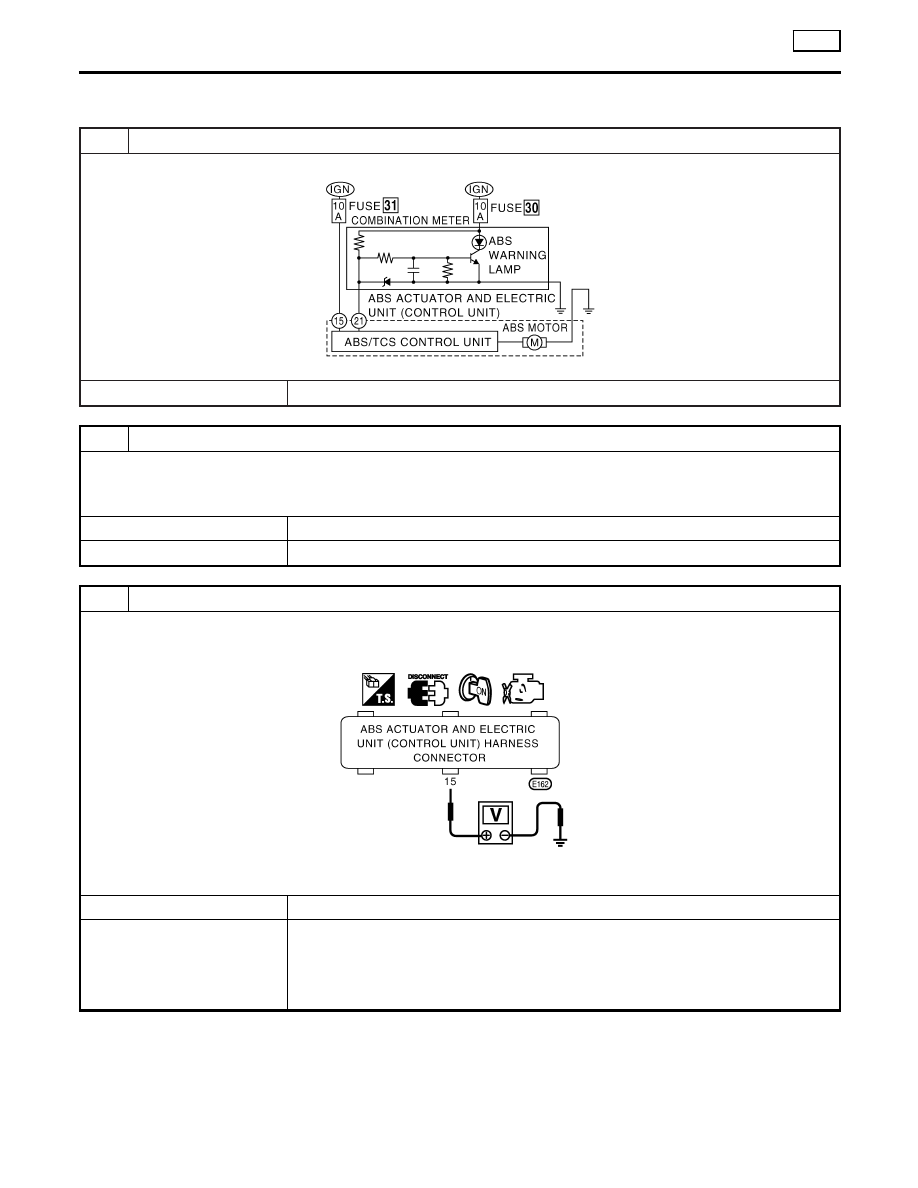
ABS control unit inspection
SBR170F
©
GO TO 2.
2
CHECK FUSE
Check 10A fuse No. 31 for ABS actuator and electric unit (control unit). For fuse layout, refer to “POWER SUPPLY ROUT-
ING” in EL section.
Is fuse OK?
Yes
©
GO TO 3.
No
©
GO TO 5.
3
CHECK ABS/TCS CONTROL UNIT POWER SUPPLY CIRCUIT
1. Disconnect connector from ABS actuator and electric unit (control unit) E162.
2. Check voltage between ABS actuator and electric unit (control unit) harness connector E162 terminal 15 (GY) and
ground after turning ignition switch “ON”.
SBR171F
Does battery voltage exist?
Yes
©
GO TO 4.
No
©
Check the following.
I
Harness connector E162
I
Harness for open or short between ABS actuator and electric unit (control unit) and
fuse
If NG, repair harness or connectors.
TROUBLE DIAGNOSES FOR SYMPTOMS
TCS
7. ABS Warning Lamp Stays On When Ignition Switch Is Turned On
BR-80
Нет комментариевНе стесняйтесь поделиться с нами вашим ценным мнением.
Текст