Infiniti I35 (A33). Manual — part 25

Items
Symptom
Condition
Diagnostic Item
Reference Page
NOT USED
Transaxle over-
heats.
ON vehicle
1. Fluid level
2. Engine idling rpm
3. Accelerator pedal position sensor
4. Line pressure test
5. Line pressure solenoid valve
6. Control valve assembly
OFF vehicle
7. Oil pump
8. Reverse clutch
9. High clutch
10. Brake band
11. Forward clutch
12. Overrun clutch
13. Low & reverse brake
14. Torque converter
ATF shoots out
during operation.
White smoke
emitted from
exhaust pipe dur-
ing operation.
ON vehicle
1. Fluid level
OFF vehicle
2. Reverse clutch
3. High clutch
4. Brake band
5. Forward clutch
6. Overrun clutch
7. Low & reverse brake
Offensive smell at
fluid charging
pipe.
ON vehicle
1. Fluid level
OFF vehicle
2. Torque converter
3. Oil pump
4. Reverse clutch
5. High clutch
6. Brake band
7. Forward clutch
8. Overrun clutch
9. Low & reverse brake
GI
MA
EM
LC
EC
FE
AX
SU
BR
ST
RS
BT
HA
SC
EL
IDX
TROUBLE DIAGNOSIS — GENERAL DESCRIPTION
Symptom Chart (Cont’d)
AT-97
AAT475A
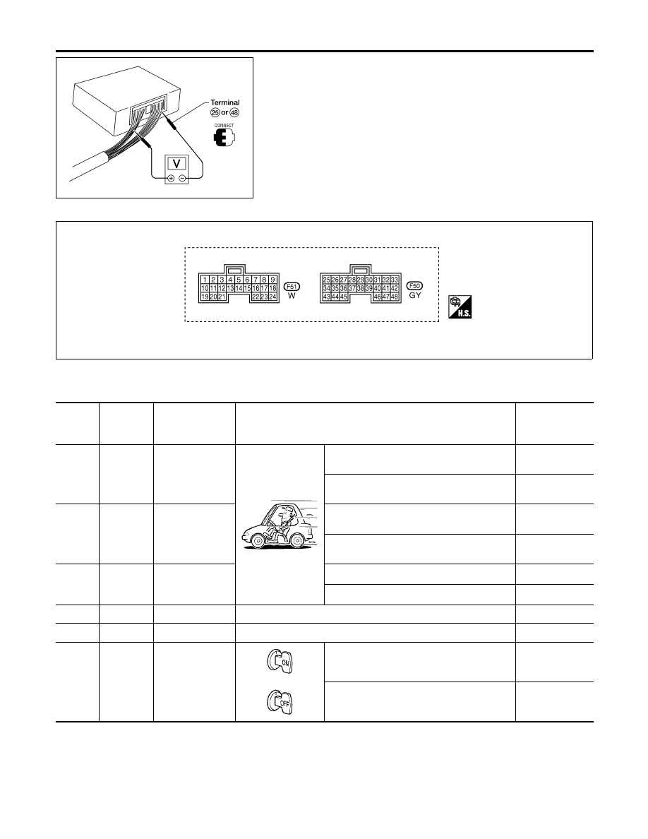
TCM Terminals and Reference Value
=NHAT0031
PREPARATION
NHAT0031S01
I
Measure voltage between each terminal and terminal 25 or 48
by following “TCM INSPECTION TABLE”.
TCM HARNESS CONNECTOR TERMINAL LAYOUT
NHAT0031S02
SAT819K
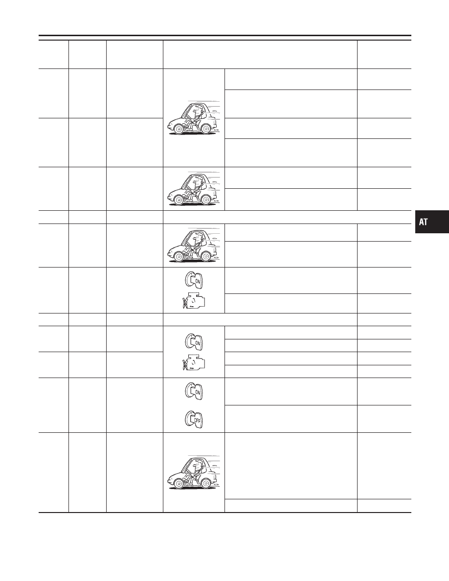
TCM INSPECTION TABLE
NHAT0031S03
(Data are reference values.)
Terminal
No.
Wire color
Item
Condition
Judgement
standard
(Approx.)
1
G/R
Line pressure
solenoid valve
When releasing accelerator pedal after warm-
ing up engine.
1.5 - 3.0V
When depressing accelerator pedal fully after
warming up engine.
0V
2
W/B
Line pressure
solenoid valve
(with dropping
resistor)
When releasing accelerator pedal after warm-
ing up engine.
4 - 14V
When depressing accelerator pedal fully after
warming up engine.
0V
3
G/B
Torque converter
clutch solenoid
valve
When A/T performs lock-up.
8 - 15V
When A/T does not perform lock-up.
0V
5
L
CAN-H (high)
—
—
6
R
CAN-L (low)
—
—
10
R/Y
Power source
or
When turning ignition switch to ON.
Battery voltage
When turning ignition switch to OFF.
0V
TROUBLE DIAGNOSIS — GENERAL DESCRIPTION
TCM Terminals and Reference Value
AT-98
Terminal
No.
Wire color
Item
Condition
Judgement
standard
(Approx.)
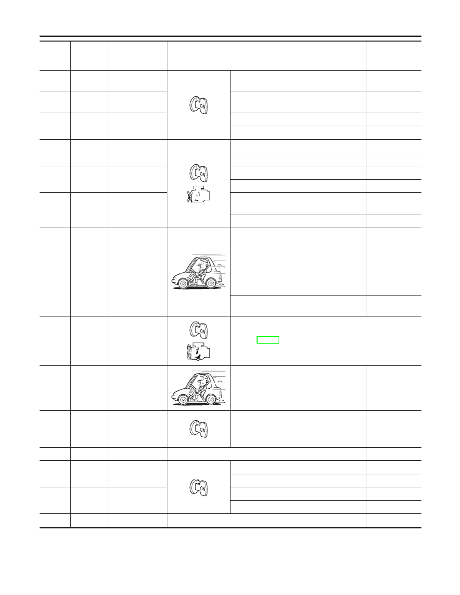
11
R/Y
Shift solenoid
valve A
When shift solenoid valve A operates.
(When driving in D
1
or D
4
.)
Battery voltage
When shift solenoid valve A does not oper-
ate.
(When driving in D
2
or D
3
.)
0V
12
LG/B
Shift solenoid
valve B
When shift solenoid valve B operates.
(When driving in D
1
or D
2
.)
Battery voltage
When shift solenoid valve B does not oper-
ate.
(When driving in D
3
or D
4
.)
0V
13
G/R
A/T CHECK indi-
cator lamp
When AT CHECK indicator lamp is ON.
0V
When AT CHECK indicator lamp is OFF.
Battery voltage
19
R/Y
Power source
Same as No. 10
20
BR/Y
Overrun clutch
solenoid valve
When overrun clutch solenoid valve operates. Battery voltage
When overrun clutch solenoid valve does not
operate.
0V
22
G/Y
3rd position switch
When the selector lever is in a position other
than 3rd position.
Battery voltage
When the selector lever is in 3rd position.
0V
25
B
Ground
—
0V
26
PU/R
PNP switch 1st
position
When setting selector lever to 1st position.
Battery voltage
When setting selector lever to other positions. 0V
27
P/B
PNP switch 2nd
position
When setting selector lever to 2nd position.
Battery voltage
When setting selector lever to other positions. 0V
28
Y/R
Power source
(Memory back-up)
or
When turning ignition switch to OFF.
Battery voltage
When turning ignition switch to ON.
Battery voltage
29
W
Revolution sensor
(VHCL/S SEN)
When moving at 20 km/h (12 MPH), use the
CONSULT-II pulse frequency measuring func-
tion.*1
CAUTION:
Connect the diagnosis data link cable to
the vehicle diagnosis connector.
*1: A circuit tester cannot be used to test this
item.
450 Hz
When vehicle parks.
0V
GI
MA
EM
LC
EC
FE
AX
SU
BR
ST
RS
BT
HA
SC
EL
IDX
TROUBLE DIAGNOSIS — GENERAL DESCRIPTION
TCM Terminals and Reference Value (Cont’d)
AT-99
Terminal
No.
Wire color
Item
Condition
Judgement
standard
(Approx.)
30*
BR/Y
Data link connec-
tor (RX)
—
—
31*
P
Data link connec-
tor (TX)
—
—
32
R
Sensor power
Ignition switch ON.
4.5 - 5.5V
Ignition switch OFF.
0V
34
Y/PU
PNP switch D
position
When setting selector lever to D position.
Battery voltage
When setting selector lever to other positions. 0V
35
G/W
PNP switch R
position
When setting selector lever to R position.
Battery voltage
When setting selector lever to other positions. 0V
36
R/G
PNP switch P or
N position
When setting selector lever to P or N posi-
tion.
Battery voltage
When setting selector lever to other positions. 0V
38
PU
Power train revo-
lution sensor
When moving at 20 km/h (12 MPH), use the
CONSULT-II pulse frequency measuring func-
tion.*1
CAUTION:
Connect the diagnosis data link cable to
the vehicle diagnosis connector.
*1: A circuit tester cannot be used to test this
item.
240 Hz
When vehicle parks.
Under 1.3V or
over 4.5V
39
W/G
Engine speed sig-
nal (TACHO)
Refer to EC-137, “ECM INSPECTION TABLE”.
40
PU/R
Vehicle speed
sensor (MTR)
When moving vehicle at 2 to 3 km/h (1 to 2
MPH) for 1 m (3 ft) or more.
Intermittently
changes
between approx.
0V and approx.
4.5V
41
W
Accelerator pedal
position sensor
When depressing accelerator pedal slowly
after warming up engine.
(Voltage rises gradually in response to
throttle position.)
Fully-closed
throttle: 0.5V
Fully-open
throttle: 4V
42
B
Sensor ground
—
0V
45
R/G
Stop lamp switch
When depressing brake pedal
Battery voltage
When releasing brake pedal
0V
47
G
A/T fluid tempera-
ture sensor
When ATF temperature is 20°C (68°F).
1.5V
When ATF temperature is 80°C (176°F).
0.5V
48
B
Ground
—
0V
*: These terminals are connected to the Data link connector.
TROUBLE DIAGNOSIS — GENERAL DESCRIPTION
TCM Terminals and Reference Value (Cont’d)
AT-100
Нет комментариевНе стесняйтесь поделиться с нами вашим ценным мнением.
Текст