Infiniti I35 (A33). Manual — part 286
6
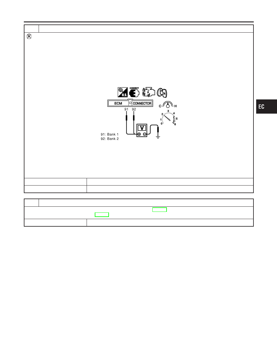
CHECK HEATED OXYGEN SENSOR 1
Without CONSULT-II
1. Start engine and warm it up to normal operating temperature.
2. Set voltmeter probes between ECM terminal 91 (HO2S1 bank 1 signal) or 92 (HO2S1 bank 2 signal) and ground.
3. Check the following with engine speed held at 2,000 rpm constant under no load.
I
The voltage fluctuates between 0 to 0.3V and 0.6 to 1.0V more than 5 times within 10 seconds.
I
The maximum voltage is over 0.6V at least one time.
I
The minimum voltage is below 0.3V at least one time.
I
The voltage never exceeds 1.0V.
1 time: 0 - 0.3V
,
0.6 - 1.0V
,
0 - 0.3V
2 times: 0 - 0.3V
,
0.6 - 1.0V
,
0 - 0.3V
,
0.6 - 1.0V
,
0 - 0.3V
SEC085D
CAUTION:
I
Discard any heated oxygen sensor which has been dropped from a height of more than 0.5 m (19.7 in) onto a
hard surface such as a concrete floor; use a new one.
I
Before installing new oxygen sensor, clean exhaust system threads using Oxygen Sensor Thread Cleaner tool
J-43897-18 or J-43897-12 and approved anti-seize lubricant.
OK or NG
OK
©
GO TO 7.
NG
©
Replace malfunctioning heated oxygen sensor 1.
7
CHECK INTERMITTENT INCIDENT
Refer to “TROUBLE DIAGNOSIS FOR INTERMITTENT INCIDENT”, EC-152.
For circuit, refer to “Wiring Diagram”, EC-238.
©
INSPECTION END
GI
MA
EM
LC
FE
AT
AX
SU
BR
ST
RS
BT
HA
SC
EL
IDX
DTC P1143, P1163 HO2S1
Diagnostic Procedure (Cont’d)
EC-485
SEF463R
SEF288D
Component Description
NHEC1154
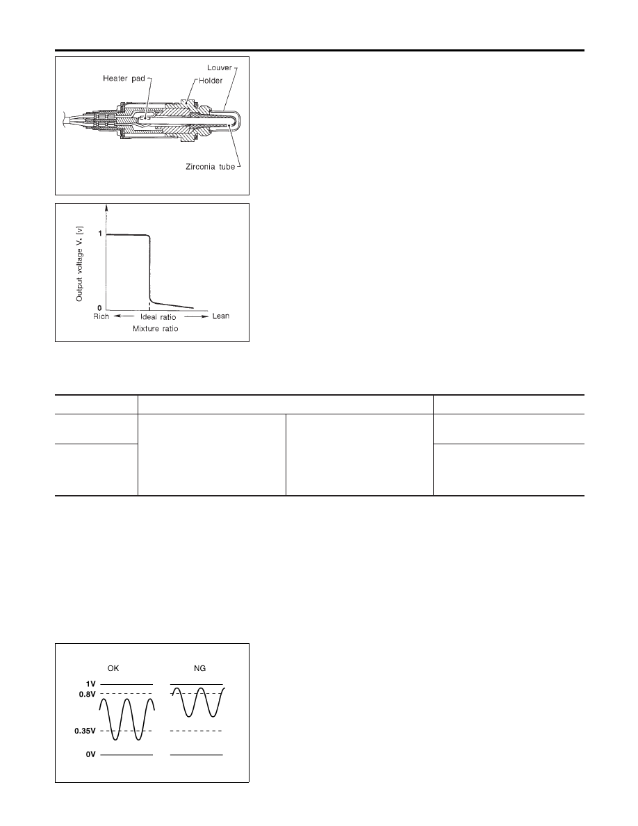
The heated oxygen sensor 1 is placed into the front tube. It detects
the amount of oxygen in the exhaust gas compared to the outside
air. The heated oxygen sensor 1 has a closed-end tube made of
ceramic zirconia. The zirconia generates voltage from approxi-
mately 1V in richer conditions to 0V in leaner conditions. The
heated oxygen sensor 1 signal is sent to the ECM. The ECM
adjusts the injection pulse duration to achieve the ideal air-fuel
ratio. The ideal air-fuel ratio occurs near the radical change from
1V to 0V.
CONSULT-II Reference Value in Data Monitor
Mode
NHEC1155
Specification data are reference values.
MONITOR ITEM
CONDITION
SPECIFICATION
HO2S1 (B1)
HO2S1 (B2)
I
Engine: After warming up
Maintaining engine speed at 2,000
rpm
0 - 0.3V
+,
Approx. 0.6 - 1.0V
HO2S1 MNTR
(B1)
HO2S1 MNTR
(B2)
LEAN
+,
RICH
Changes more than 5 times during
10 seconds.
SEF299U
On Board Diagnosis Logic
NHEC1157
To judge the malfunction, the output from the heated oxygen sen-
sor 1 is monitored to determine whether the “rich” output is suffi-
ciently high and “lean” output is sufficiently low. When both the
outputs are shifting to the rich side, the malfunction will be
detected.
DTC P1144, P1164 HO2S1
Component Description
EC-486
DTC No.
Trouble diagnosis
name
DTC Detecting Condition
Possible Cause
P1144
1144
(Bank 1)
P1164
1164
(Bank 2)
Heated oxygen sen-
sor 1 rich shift moni-
toring
The maximum and minimum voltages from the
sensor are beyond the specified voltages.
I
Heated oxygen sensor 1
I
Fuel pressure
I
Injectors
I
Heated oxygen sensor 1 heater
DTC Confirmation Procedure
NHEC1158
CAUTION:
Always drive vehicle at a safe speed.
NOTE:
If DTC Confirmation Procedure has been previously conducted,
always turn ignition switch OFF and wait at least 10 seconds before
conducting the next test.
TESTING CONDITION:
I
Always perform at a temperature above −10°C (14°F).
I
Before performing the following procedure, confirm that
battery voltage is more than 11V at idle.
PBIB0548E
PBIB0549E
SEC772C
WITH CONSULT-II
NHEC1158S01
1)
Start engine and warm it up to normal operating temperature.
2)
Stop engine and wait at least 5 seconds.
3)
Turn ignition switch ON and select “HO2S1 (B1)/(B2) P1144/
P1164” of “HO2S1” in “DTC WORK SUPPORT” mode with
CONSULT-II.
4)
Touch “START”.
5)
Start engine and let it idle for at least 3 minutes.
NOTE:
Never raise engine speed above 3,600 rpm after this step. If
the engine speed limit is exceeded, return to step 5.
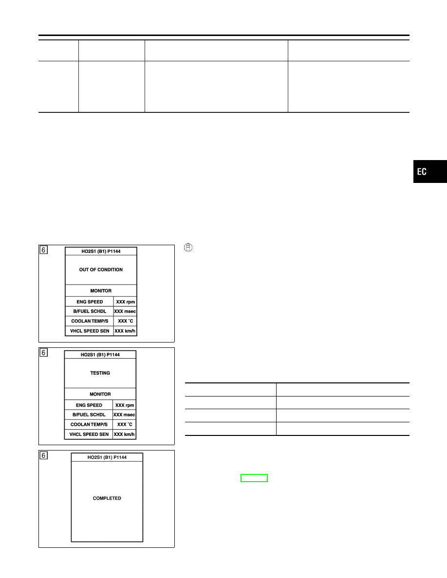
6)
When the following conditions are met, “TESTING” will be dis-
played on the CONSULT-II screen. Maintain the conditions
continuously until “TESTING” changes to “COMPLETED”. (It
will take approximately 50 seconds or more.)
ENG SPEED
1,200 - 2,600 rpm
Vehicle speed
Less than 100 km/h (62 MPH)
B/FUEL SCHDL
3 - 9 msec
Selector lever
Suitable position
If “TESTING” is not displayed after 5 minutes, retry from
step 2.
7)
Make sure that “OK” is displayed after touching “SELF-DIAG
RESULTS”.
If
“NG”
is
displayed,
refer
to
“Diagnostic
Procedure”, EC-488.
GI
MA
EM
LC
FE
AT
AX
SU
BR
ST
RS
BT
HA
SC
EL
IDX
DTC P1144, P1164 HO2S1
On Board Diagnosis Logic (Cont’d)
EC-487
SEC902C
Overall Function Check
NHEC1159
Use this procedure to check the overall function of the heated oxy-
gen sensor 1 circuit. During this check, a 1st trip DTC might not be
confirmed.
WITH GST
NHEC1159S01
1)
Start engine and warm it up to normal operating temperature.
2)
Set voltmeter probes between ECM terminal 91 (HO2S1 bank
1 signal) or 92 (HO2S1 bank 2 signal) and ground.
3)
Check one of the following with engine speed held at 2,000
rpm constant under no load.
I
The maximum voltage is below 0.8V at least one time.
I
The minimum voltage is below 0.35V at least one time.
4)
If NG, go to “Diagnostic Procedure”, EC-488.
Diagnostic Procedure
NHEC1160
1
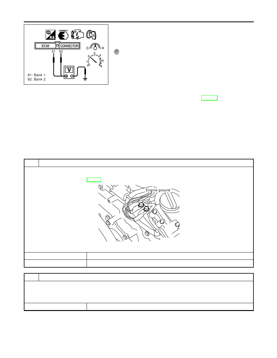
CHECK GROUND CONNECTIONS
1. Turn ignition switch OFF.
2. Loosen and retighten two engine ground screws.
Refer to “Ground Inspection”, EC-160.
SEC047D
OK or NG
OK
©
GO TO 2.
NG
©
Repair or replace ground connections.
2
RETIGHTEN HEATED OXYGEN SENSOR 1
Loosen and retighten corresponding heated oxygen sensor 1.
Tightening torque:
40 - 60 N·m (4.1 - 6.1 kg-m, 30 - 44 ft-lb)
©
GO TO 3.
DTC P1144, P1164 HO2S1
Overall Function Check
EC-488
Нет комментариевНе стесняйтесь поделиться с нами вашим ценным мнением.
Текст