Infiniti I35 (A33). Manual — part 293
Description
NHEC1521
The malfunction information related to ABS/TCS or VDC/TCS/ABS is transferred through the CAN communi-
cation line from ABS/TCS control unit or VDC/TCS/ABS control unit to ECM.
Be sure to erase the malfunction information such as DTC not only for ABS/TCS control unit or VDC/
TCS/ABS control unit but also for ECM after the ABS/TCS or VDC/TCS/ABS related repair.
On Board Diagnosis Logic
NHEC1522
Freeze frame data is not stored in the ECM for this self-diagnosis. The MIL will not light up for this
self-diagnosis.
DTC No.
Trouble diagnosis name
DTC detecting condition
Possible cause
P1211
1211
VDC/TCS/ABS control
unit performance
ECM receives a malfunction information from
ABS/TCS control unit or VDC/TCS/ABS con-
trol unit.
I
ABS/TCS control unit
I
VDC/TCS/ABS control unit
I
TCS related parts
I
VDC related parts
DTC Confirmation Procedure
NHEC1523
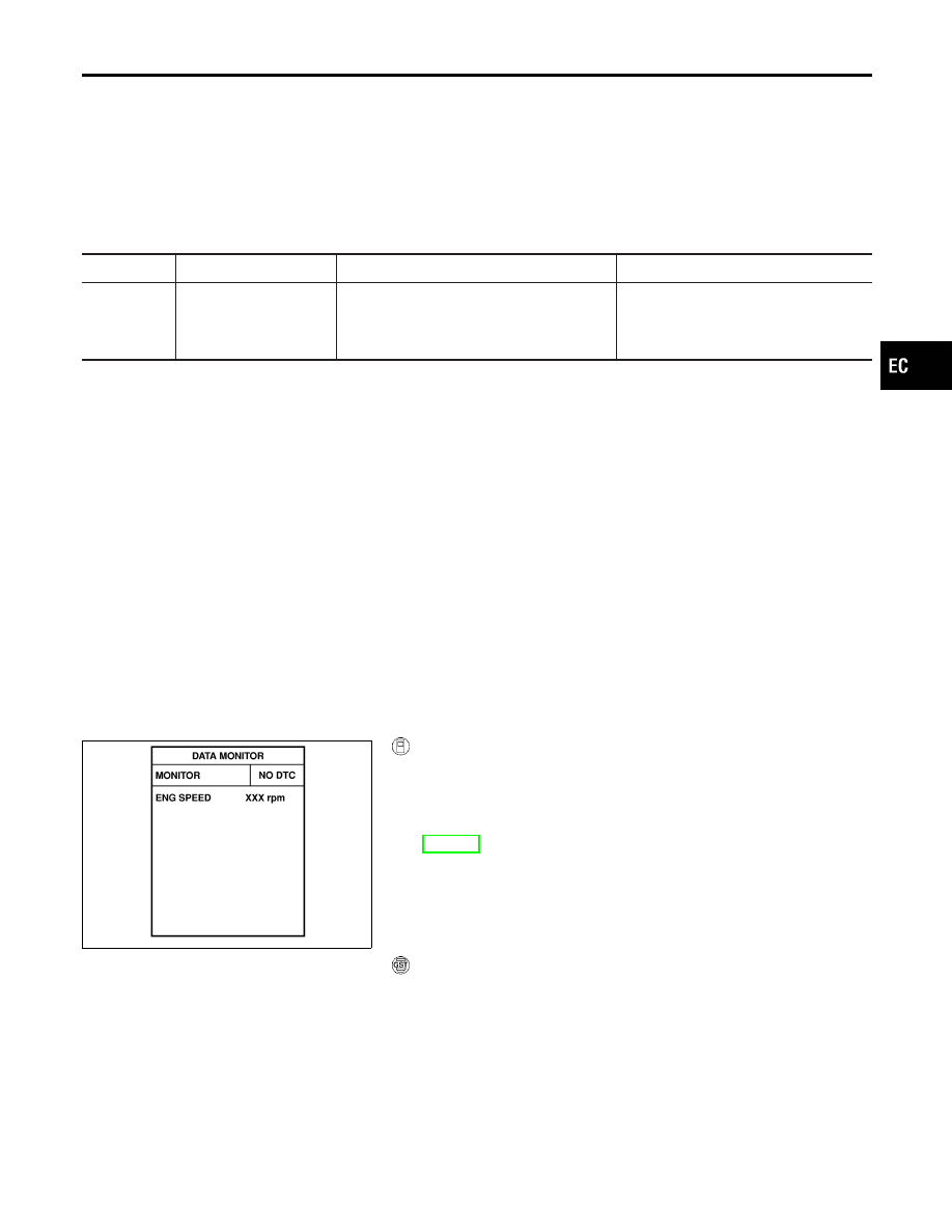
TESTING CONDITION:
Before performing the following procedure, confirm that bat-
tery voltage is more than 10.5V at idle.
SEF058Y
With CONSULT-II
1.
Turn ignition switch ON.
2.
Select “DATA MONITOR” mode with CONSULT-II.
3.
Start engine and let it idle for at least 60 seconds.
4.
If 1st trip DTC is detected, go to “Diagnostic Procedure”,
EC-514.
WITH GST
Follow the procedure “WITH CONSULT-II” above.
GI
MA
EM
LC
FE
AT
AX
SU
BR
ST
RS
BT
HA
SC
EL
IDX
DTC P1211 VDC/TCS/ABS CONTROL UNIT
Description
EC-513
Diagnostic Procedure
NHEC1524
Go to BR-53 (With ABS/TCS models) or BR-100 (With VDC/TCS/
ABS models), “TROUBLE DIAGNOSIS — INTRODUCTION”.
DTC P1211 VDC/TCS/ABS CONTROL UNIT
Diagnostic Procedure
EC-514
Description
NHEC1525
NOTE:
If DTC P1212 is displayed with DTC U1000, U1001, first perform the trouble diagnosis for DTC U1000,
U1001. Refer to “DTC U1000, U1001 CAN COMMUNICATION LINE”, EC-162.
This CAN communication line is used to control the smooth engine operation during the VDC, ABS or TCS
operation. Pulse signals are exchanged between ECM and ABS/TCS control unit or VDC/TCS/ABS control
unit.
Be sure to erase the malfunction information such as DTC not only in ABS/TCS control unit or VDC/
TCS/ABS control unit but also ECM after the ABS/TCS or VDC/TCS/ABS related repair.
On Board Diagnosis Logic
NHEC1526
Freeze frame data is not stored in the ECM for this self-diagnosis. The MIL will not light up for this
self-diagnosis.
DTC No.
Trouble diagnosis name
DTC detecting condition
Possible cause
P1212
1212
VDC/TCS/ABS communi-
cation line
ECM cannot receive the information from
ABS/TCS control unit or VDC/TCS/ABS con-
trol unit continuously.
I
Harness or connectors
(The CAN communication line is open
or shorted.)
I
ABS/TCS control unit
I
VDC/TCS/ABS control unit
I
Dead (Weak) battery
DTC Confirmation Procedure
NHEC1527
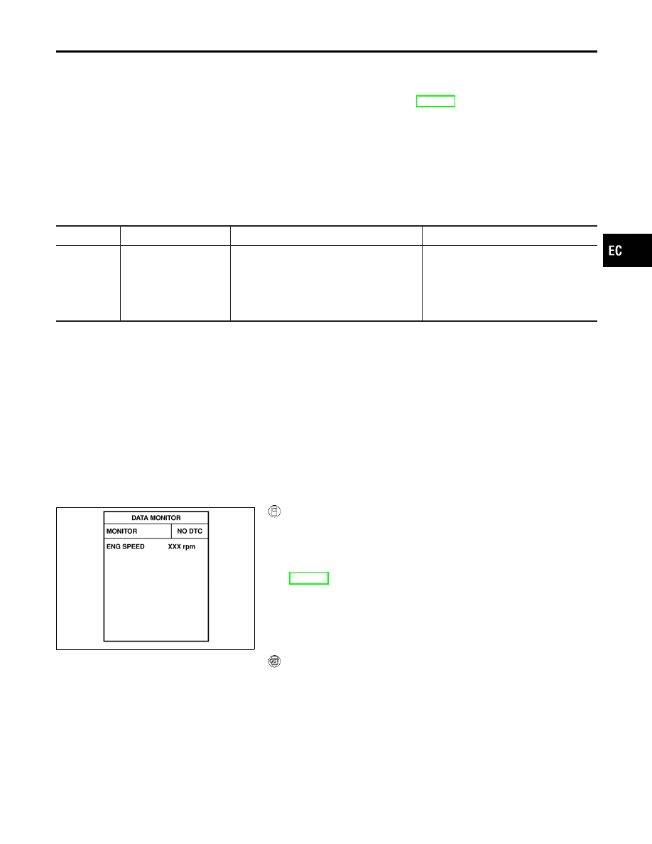
TESTING CONDITION:
Before performing the following procedure, confirm that bat-
tery voltage is more than 10.5V at idle.
SEF058Y
WITH CONSULT-II
1.
Turn ignition switch ON.
2.
Select “DATA MONITOR” mode with CONSULT-II.
3.
Start engine and let it idle for at least 10 seconds.
4.
If 1st trip DTC is detected, go to “Diagnostic Procedure”,
EC-516.
WITH GST
Follow the procedure “WITH CONSULT-II” above.
GI
MA
EM
LC
FE
AT
AX
SU
BR
ST
RS
BT
HA
SC
EL
IDX
DTC P1212 VDC/TCS/ABS COMMUNICATION LINE
Description
EC-515

Нет комментариевНе стесняйтесь поделиться с нами вашим ценным мнением.
Текст