Infiniti I35 (A33). Manual — part 493
SEM947G
6.
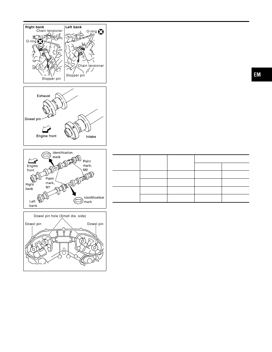
Install camshaft chain tensioners on both sides of cylinder
head.
KBIA1071E
7.
Install exhaust and intake camshafts and camshaft brackets.
I
Exhaust camshaft has a dowel pin on camshaft sprocket
mounting flange. Install it on the exhaust side.
SEM653F
I
Identification marks are present on camshafts.
Bank
INT/EXH
ID mark
Paint mark
M1
M2
RH
INT
RE
Yes
No
EXH
RE
No
Yes
LH
INT
LH
Yes
No
EXH
LH
No
Yes
KBIA1072E
I
Position camshaft
RH exhaust camshaft dowel pin at about 10 o’clock
LH exhaust camshaft dowel pin at about 2 o’clock
GI
MA
LC
EC
FE
AT
AX
SU
BR
ST
RS
BT
HA
SC
EL
IDX
CYLINDER HEAD
Installation (Cont’d)
EM-63
SEM564G
SEM446G
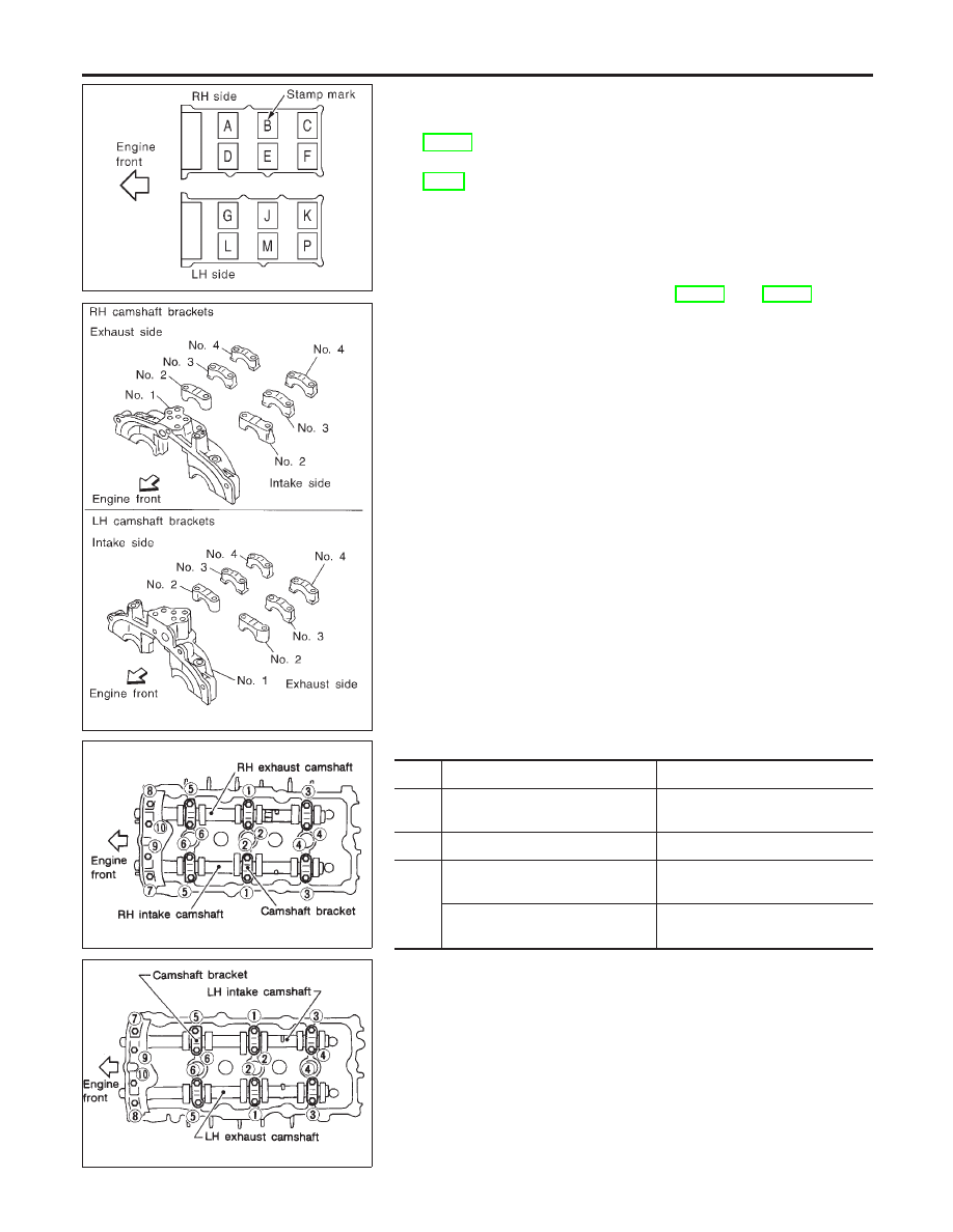
8.
Before installing camshaft brackets, apply sealant to mating
surface of No. 1 camshaft bracket.
I
Refer to “POSITION FOR APPLYING LIQUID GASKET”,
EM-31.
I
Use Genuine RTV silicone sealant or equivalent. Refer to
GI-53.
I
Install camshaft brackets in their original positions.
Align stamp mark as shown in the figure.
I
If any part of valve assembly or camshaft is replaced,
check valve clearance according to reference data.
After completing assembly check valve clearance. Refer
to “Checking” and “Adjusting”, EM-66 and EM-68.
Reference data valve clearance (Cold):
Intake
0.26 - 0.34 mm (0.010 - 0.013 in)
Exhaust
0.29 - 0.37 mm (0.011 - 0.015 in)
I
Lubricate threads and seat surfaces of camshaft bracket
bolts with new engine oil before installing them.
SEM885EA
SEM886EA
I
Tighten the camshaft brackets in the following steps.
Step
Tightening torque
Tightening order
1
1.96 N·m (0.2 kg-m, 17 in-lb)
Tighten in the order of 7 to 10,
then tighten 1 to 6.
2
5.88 N·m (0.6 kg-m, 52 in-lb)
Tighten in the numerical order.
3
9.02 - 11.8 N·m (0.92 - 1.20 kg-m,
79.9 - 104.2 in-lb)
Tighten in the order of 1 to 6.
8.3 - 10.3 N·m (0.9 - 1.0 kg-m,
74 - 91 in-lb)
Tighten in the order of 7 to 10.
CYLINDER HEAD
Installation (Cont’d)
EM-64
SEM443GB
9.
Install intake valve timing control solenoid valves.
PBIC0788E
10. Install O-rings to cylinder block.
SEM945G
11. Install O-rings to cylinder head.
12. Apply sealant to the hatched portion of rear timing chain case.
Refer to “POSITION FOR APPLYING LIQUID GASKET”,
EM-31.
I
Apply continuous bead of liquid gasket to mating surface of
rear timing chain case.
I
Before installation, wipe off the protruding sealant.
SEM735G
13. Align rear timing chain case with dowel pins, then install on
cylinder head and block.
14. Tighten rear chain case bolts.
a.
Tighten bolts in numerical order shown in the figure with
smaller torque than specified.
b.
Tighten bolts to the specified torque repeating above step a.
15. Reinstall all removed parts in reverse order of removal.
GI
MA
LC
EC
FE
AT
AX
SU
BR
ST
RS
BT
HA
SC
EL
IDX
CYLINDER HEAD
Installation (Cont’d)
EM-65
SEM918G
Valve Clearance
NHEM0049
CHECKING
NHEM0049S01
Check valve clearance while engine is cold and not running.
1.
Remove ornament cover.
2.
Remove air duct with air cleaner case, collectors, hoses, wires,
harnesses, connectors and so on.
3.
Remove intake manifold collectors. Refer to EM-11, “TIGHT-
ENING PROCEDURES”.
4.
Remove ignition coils and spark plugs.
5.
Remove RH and LH rocker covers. Refer to EM-21,
“Removal”.
6.
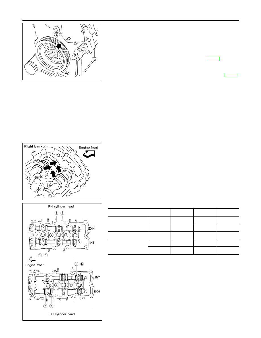
Set No. 1 cylinder at TDC on its compression stroke.
I
Align pointer with TDC mark on crankshaft pulley.
SEM418G
I
Check that valve lifters on No. 1 cylinder are loose and valve
lifters on No. 4 are tight.
If not, turn crankshaft one revolution (360°) and align as
shown.
SEM893E
7.
Check only those valves shown in the figure.
Measuring position (RH bank)
No. 1 CYL
No. 3 CYL
No. 5 CYL
No. 1 cylinder at TDC
EXH
X
INT
X
Measuring position (LH bank)
No. 2 CYL
No. 4 CYL
No. 6 CYL
No. 1 cylinder at TDC
INT
X
EXH
X
CYLINDER HEAD
Valve Clearance
EM-66
Нет комментариевНе стесняйтесь поделиться с нами вашим ценным мнением.
Текст