Infiniti I35 (A33). Manual — part 422
SEL007Y
MAIN POWER SUPPLY AND GROUND CIRCUIT CHECK
=NHEL0193S02
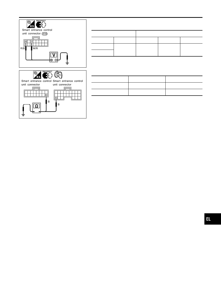
Main Power Supply Circuit Check
NHEL0193S0201
Terminals
Ignition switch
(+)
(–)
OFF
ACC
ON
49
Ground
Battery volt-
age
Battery volt-
age
Battery volt-
age
51
SEL008Y
Ground Circuit Check
NHEL0193S0202
Connector
Terminals
Continuity
M144
43 - Ground
Yes
M145
64 - Ground
Yes
GI
MA
EM
LC
EC
FE
AT
AX
SU
BR
ST
RS
BT
HA
SC
IDX
POWER DOOR LOCK
Trouble Diagnoses (Cont’d)
EL-289
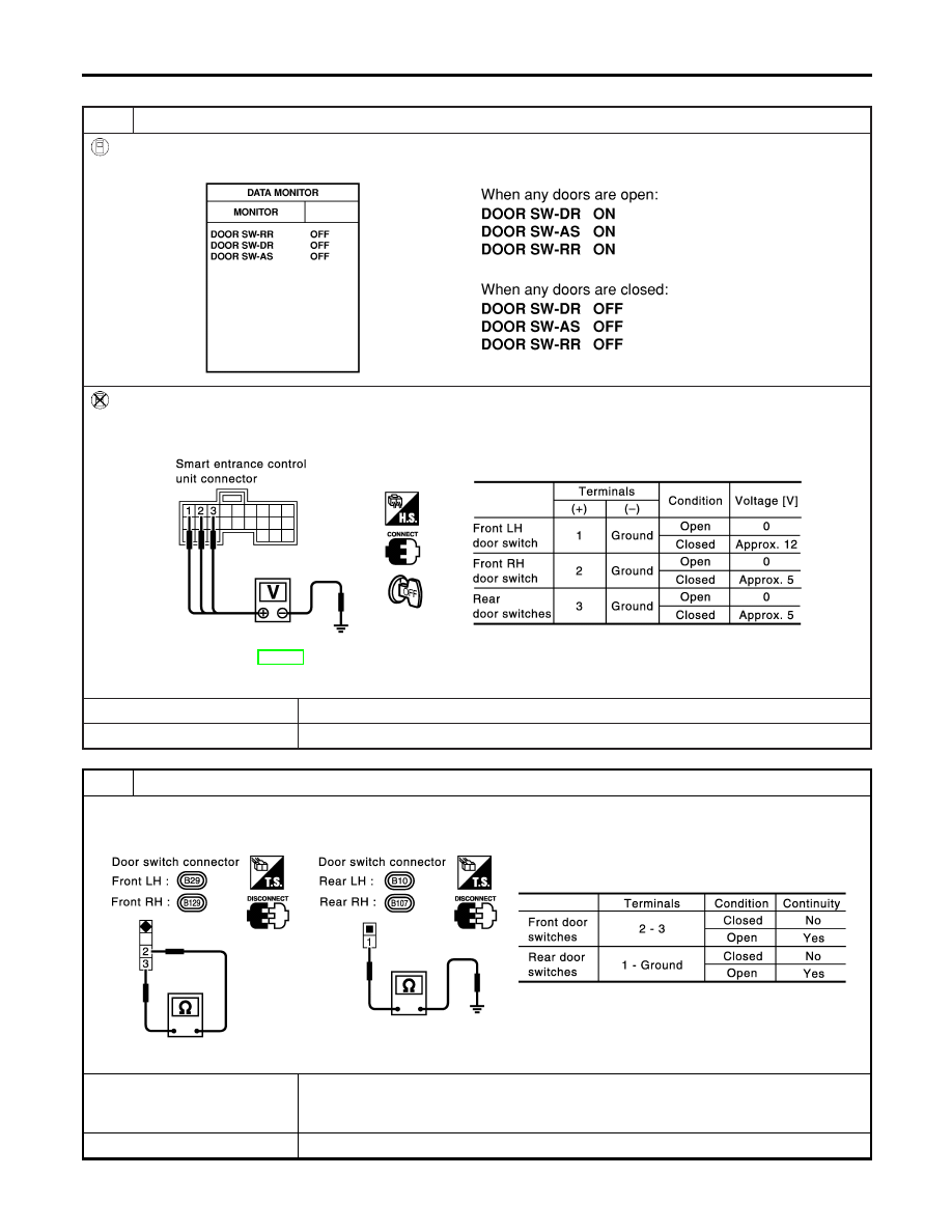
DOOR SWITCH CHECK
=NHEL0193S03
1
CHECK DOOR SWITCHES INPUT SIGNAL
With CONSULT-II
Check door switches (“DOOR SW-DR”, “DOOR SW-AS”, “DOOR SW-RR”) in “DATA MONITOR” mode with CONSULT-II.
SEL009Y
Without CONSULT-II
Check voltage between smart entrance control unit harness connector M143 terminals 1 (LG), 2 (R/L) or 3 (R/W) and
ground.
SEL010YB
Refer to wiring diagram in EL-282.
OK or NG
OK
©
Door switch is OK.
NG
©
GO TO 2.
2
CHECK DOOR SWITCHES
1. Disconnect door switch harness connector.
2. Check continuity between door switch connector terminals.
SEL900Y
OK or NG
OK
©
Check the following.
I
Door switch ground circuit or door switch ground condition
I
Harness for open or short between smart entrance control unit and door switch
NG
©
Replace door switch.
POWER DOOR LOCK
Trouble Diagnoses (Cont’d)
EL-290
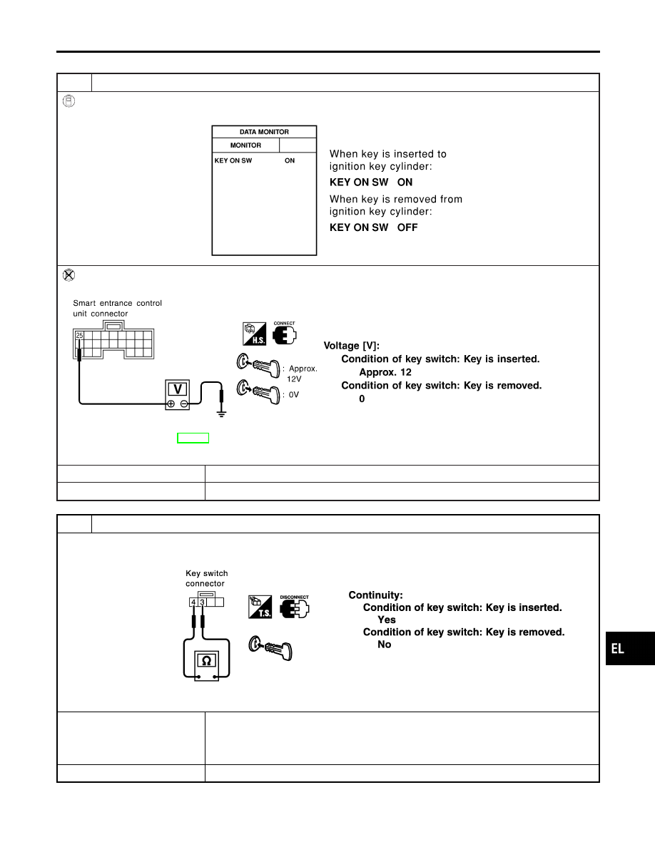
KEY SWITCH (INSERT) CHECK
=NHEL0193S04
1
CHECK KEY SWITCH INPUT SIGNAL
With CONSULT-II
Check key switch (“KEY ON SW”) in “DATA MONITOR” mode with CONSULT-II.
SEL315W
Without CONSULT-II
Check voltage between smart entrance control unit harness connector M144 terminal 25 (B/R) and ground.
SEL011Y
Refer to wiring diagram in EL-282.
OK or NG
OK
©
Key switch is OK.
NG
©
GO TO 2.
2
CHECK KEY SWITCH (INSERT)
Check continuity between key switch harness connector E154 terminals 3 and 4.
SEL549YA
OK or NG
OK
©
Check the following.
I
10A fuse [No. 13, located in fuse block (J/B)]
I
Harness for open or short between key switch and fuse
I
Harness for open or short between smart entrance control unit and key switch
NG
©
Replace key switch.
GI
MA
EM
LC
EC
FE
AT
AX
SU
BR
ST
RS
BT
HA
SC
IDX
POWER DOOR LOCK
Trouble Diagnoses (Cont’d)
EL-291
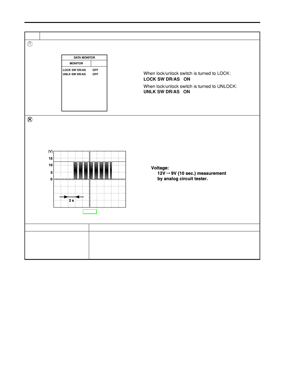
DOOR LOCK/UNLOCK SWITCH CHECK
=NHEL0193S05
1
CHECK DOOR LOCK/UNLOCK SWITCH INPUT SIGNAL
With CONSULT-II
Check door lock/unlock switch (“LOCK SW DR/AS”/“UNLK SW DR/AS”) in “DATA MONITOR” mode with CONSULT-II.
SEL341W
Without CONSULT-II
1. Remove key from ignition switch.
2. Check the signal between smart entrance control unit harness connector M144 terminal 33 (L) and ground with oscillo-
scope when door lock/unlock switch is turned “LOCK” or “UNLOCK”.
3. Make sure signals which are shown in the figure below can be detected during 10 sec. just after door lock/unlock
switch is turned “LOCK” or “UNLOCK”.
SEL396Y
Refer to wiring diagram in EL-283.
OK or NG
OK
©
Door lock/unlock switch is OK.
NG
©
Check the following.
I
Ground circuit for each front power window switch
I
Harness for open or short between each front power window switch and smart
entrance control unit connector
If above systems are normal, replace the front power window switch.
POWER DOOR LOCK
Trouble Diagnoses (Cont’d)
EL-292
Нет комментариевНе стесняйтесь поделиться с нами вашим ценным мнением.
Текст