Infiniti I35 (A33). Manual — part 448
DIAGNOSTIC PROCEDURE 7
=NHEL0177S13
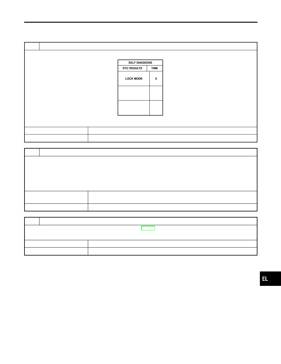
Self-diagnostic results:
“LOCK MODE” displayed on CONSULT-II screen
1
CONFIRM SELF-DIAGNOSTIC RESULTS
Confirm SELF-DIAGNOSTIC RESULTS “LOCK MODE” is displayed on CONSULT-II screen.
SEL295W
Is CONSULT-II screen displayed as above?
Yes
©
GO TO 2.
No
©
GO TO SYMPTOM MATRIX CHART 1.
2
ESCAPE FROM LOCK MODE
1. Turn ignition switch OFF.
2. Turn ignition switch ON with registered key. (Do not start engine.) Wait 5 seconds.
3. Return the key to OFF position.
4. Repeat steps 2 and 3 twice (total of three cycles).
5. Start the engine.
Does engine start?
Yes
©
System is OK.
(Now system is escaped from “LOCK MODE”.)
No
©
GO TO 3.
3
CHECK IMMU ILLUSTRATION
Check IMMU installation. Refer to “How to Replace IMMU” in EL-394.
OK or NG
OK
©
GO TO 4.
NG
©
Reinstall IMMU correctly.
GI
MA
EM
LC
EC
FE
AT
AX
SU
BR
ST
RS
BT
HA
SC
IDX
IVIS (INFINITI VEHICLE IMMOBILIZER SYSTEM — NATS)
Trouble Diagnoses (Cont’d)
EL-393
4
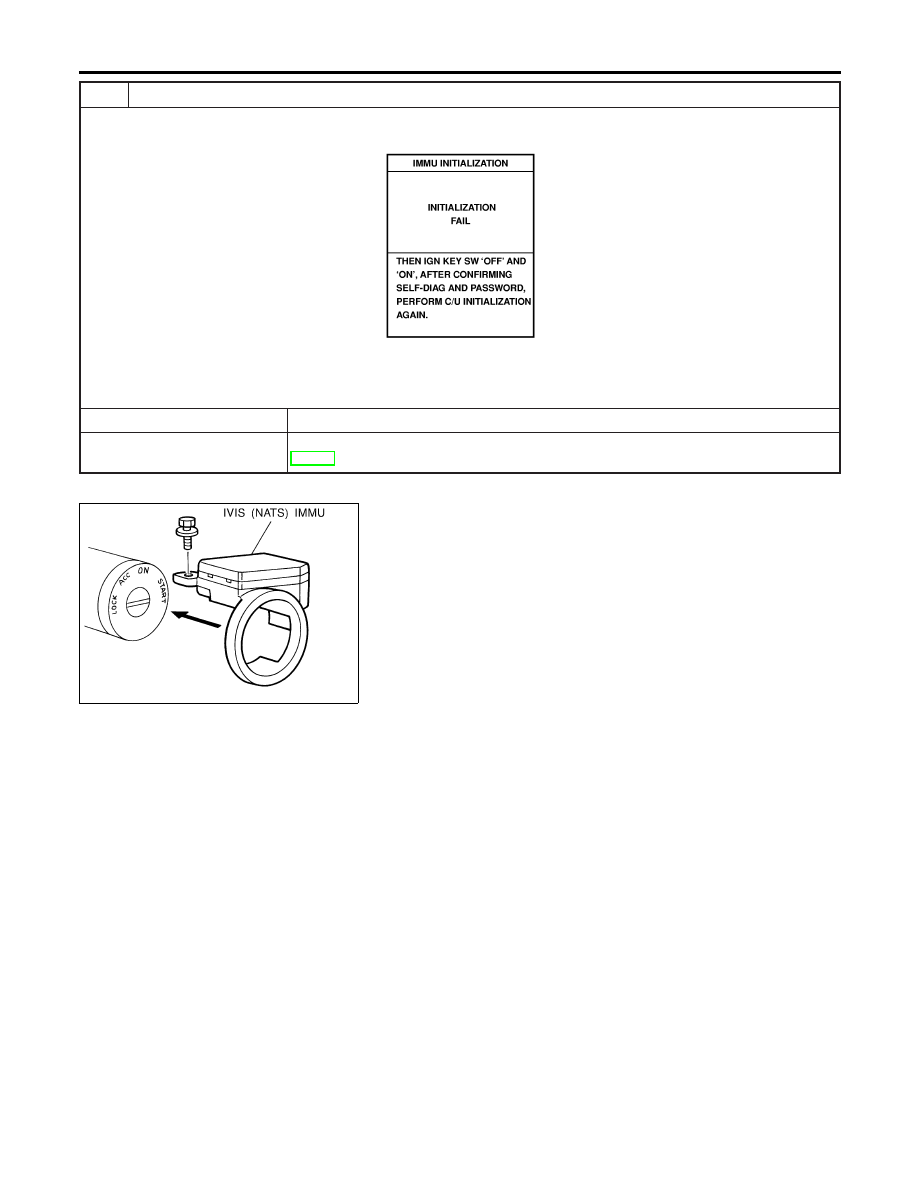
PERFORM INITIALIZATION WITH CONSULT-II
Perform initialization with CONSULT-II.
For initialization, refer to “CONSULT-II operation manual IVIS/NVIS”.
SEL297W
NOTE:
If the initialization is not completed or fails, CONSULT-II shows the above message on the screen.
Can the system be initialized?
Yes
©
System is OK.
No
©
GO TO DIAGNOSTIC PROCEDURE 5 to check “CHAIN OF IMMU-KEY”, refer to
EL-389.
SEL096WB
How to Replace IVIS (NATS) IMMU
NHEL0178
NOTE:
I
If IVIS (NATS) IMMU is not installed correctly, IVIS (NATS)
system
will
not
operate
properly
and
SELF-DIAG
RESULTS on CONSULT-II screen will show “LOCK MODE”
or “CHAIN OF IMMU-KEY”.
IVIS (INFINITI VEHICLE IMMOBILIZER SYSTEM — NATS)
Trouble Diagnoses (Cont’d)
EL-394
Precautions
NHEL0295
WARNING:
Do not attempt to disassemble the monitor. Parts of the monitor have high voltages that can result in
severe and dangerous electric shock.
CAUTION:
I
Do not reverse battery connections.
I
Do not attach unauthorized parts.
I
Protect the unit from severe impact.
NOTE:
Before beginning repair, determine whether or not the unit is defective. Refer to “This Condition Is Not
Abnormal” (EL-438).
SEL504X
System Description
NHEL0296
OUTLINE
NHEL0296S01
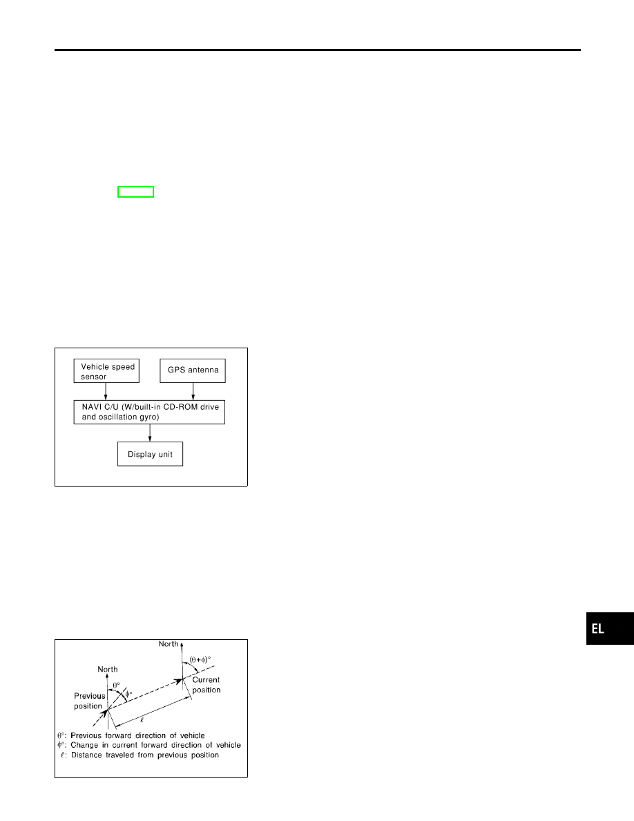
The Navigation System (Multi-AV System) relies upon three sens-
ing devices in order to determine vehicle location at regular time
intervals.
1.
Vehicle speed sensor: Determines the distance the vehicle has
traveled.
2.
Gyro (Angular velocity sensor): Determines vehicle steering
angle and directional change.
3.
GPS antenna (GPS data): Determines vehicle forward move-
ment and direction.
The data provided by the three sensing functions together with a
comparison of the mapping information read from the CD-ROM
drive permit accurate determination of the vehicle’s current location
and subsequent course (map matching). The information appears
on a liquid crystal display.
This comparison of GPS data (vehicle position sensing) and map
matching permits precise determination of vehicle location.
SEL684V
Position Sensor Operating Principles
NHEL0296S0101
The sensor determines current vehicle location by calculating the
previously sensed position, the distance traveled from this position,
and the directional changes occurring during this travel.
1.
Distance traveled
The distance traveled is calculated using signals received from
the vehicle speed sensor. The sensor automatically compen-
sates for the slightly reduced wheel and tire diameter resulting
from tire wear.
2.
Forward movement (Direction)
Changes in the direction of forward movement are calculated
GI
MA
EM
LC
EC
FE
AT
AX
SU
BR
ST
RS
BT
HA
SC
IDX
NAVIGATION SYSTEM
Precautions
EL-395
by the gyro (angular velocity sensor) and the GPS antenna
(GPS data). Each of these functions has its advantage and
disadvantages. Depending upon conditions, one function takes
precedence over the other to accurately determine the direc-
tion of forward movement.
Function type
Advantage
Disadvantage
Gyro (Angular
velocity sen-
sor)
I
Able to accurately detect
minute changes in steering
angle and direction.
I
Calculation errors may
accumulate over a long
period of continuous
vehicle travel.
GPS antenna
(GPS data)
I
Able to sense vehicle travel
in four general directions
(North, South, East, and
West)
I
Unable to detect direction
of vehicle travel at low
vehicle speeds.
SEL685V
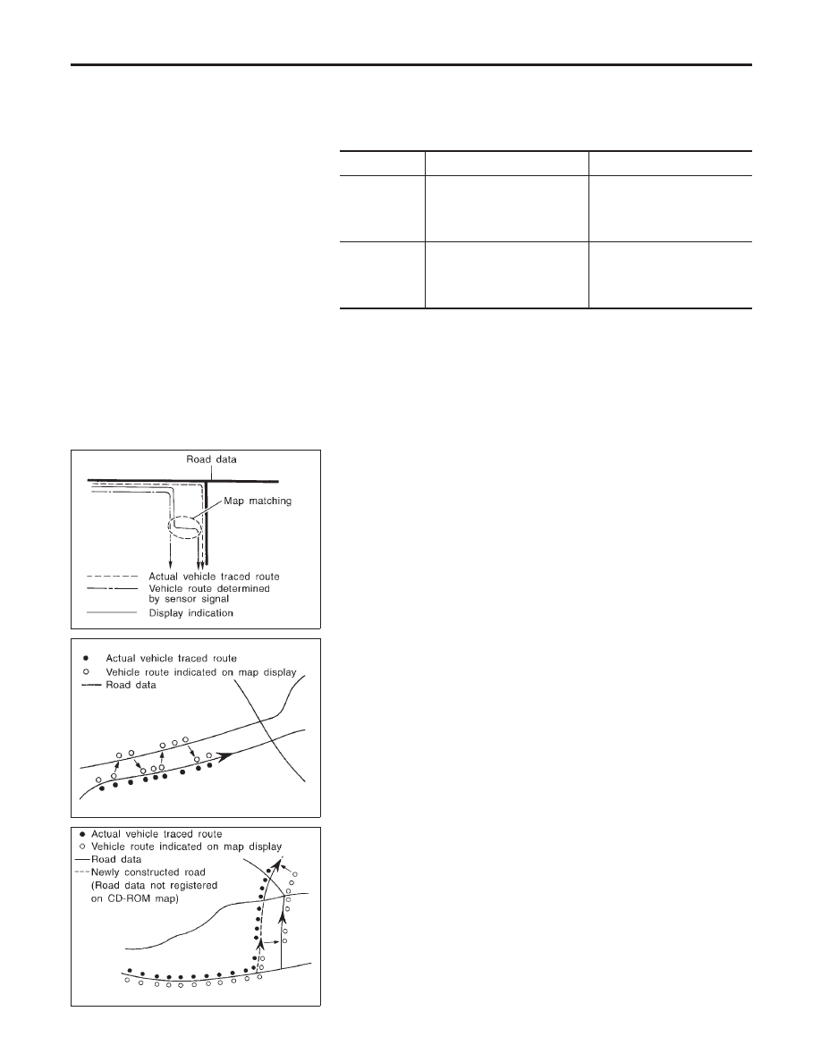
Map Matching
NHEL0296S0102
Map matching allows the driver to compare the sensed vehicle
location data with the road map contained in the CD-ROM drive.
Vehicle position is marked on the CD-ROM map. This permits the
driver to accurately determine his/her present position on the high-
way and to make appropriate course decisions.
When GPS data reception is poor during travel, the vehicle posi-
tion is not amended. At this time, manual manipulation of the CD-
ROM map position marker is required.
SEL686V
Map matching permits the driver to make priority judgments about
possible appropriate roads other than the one currently being trav-
eled.
If there is an error in the distance or direction of travel, there will
also be an error in the relative position of other routes. When two
routes are closely parallel to one another, the indicated position for
both routes will be nearly the same priority. This is so that, slight
changes in the steering direction may cause the marker to indicate
both routes alternately.
SEL687V
Newly constructed roads may not appear on the CD-ROM map. In
this case, map matching is not possible. Changes in the course of
a road will also prevent accurate map matching.
When driving on a road not shown on the CD-ROM map, the posi-
tion marker used for map matching may indicate a different route.
Even after returning to a route shown on the map, the position
marker may jump to the position currently detected.
NAVIGATION SYSTEM
System Description (Cont’d)
EL-396
Нет комментариевНе стесняйтесь поделиться с нами вашим ценным мнением.
Текст