Infiniti I35 (A33). Manual — part 115
SBR904EC
GI
MA
EM
LC
EC
FE
AT
AX
SU
ST
RS
BT
HA
SC
EL
IDX
DESCRIPTION
TCS
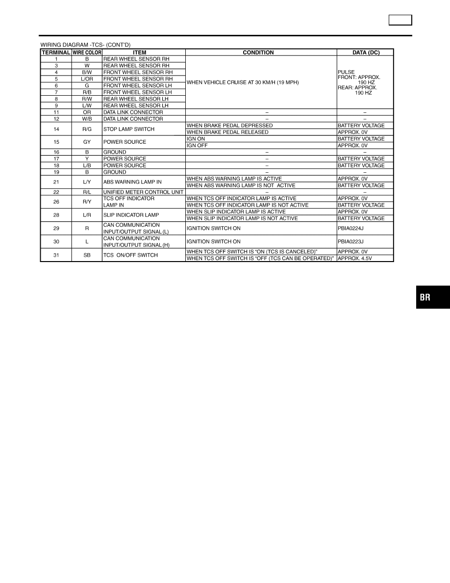
Wiring Diagram — TCS — (Cont’d)
BR-45
CONSULT-II Functions
NHBR0151
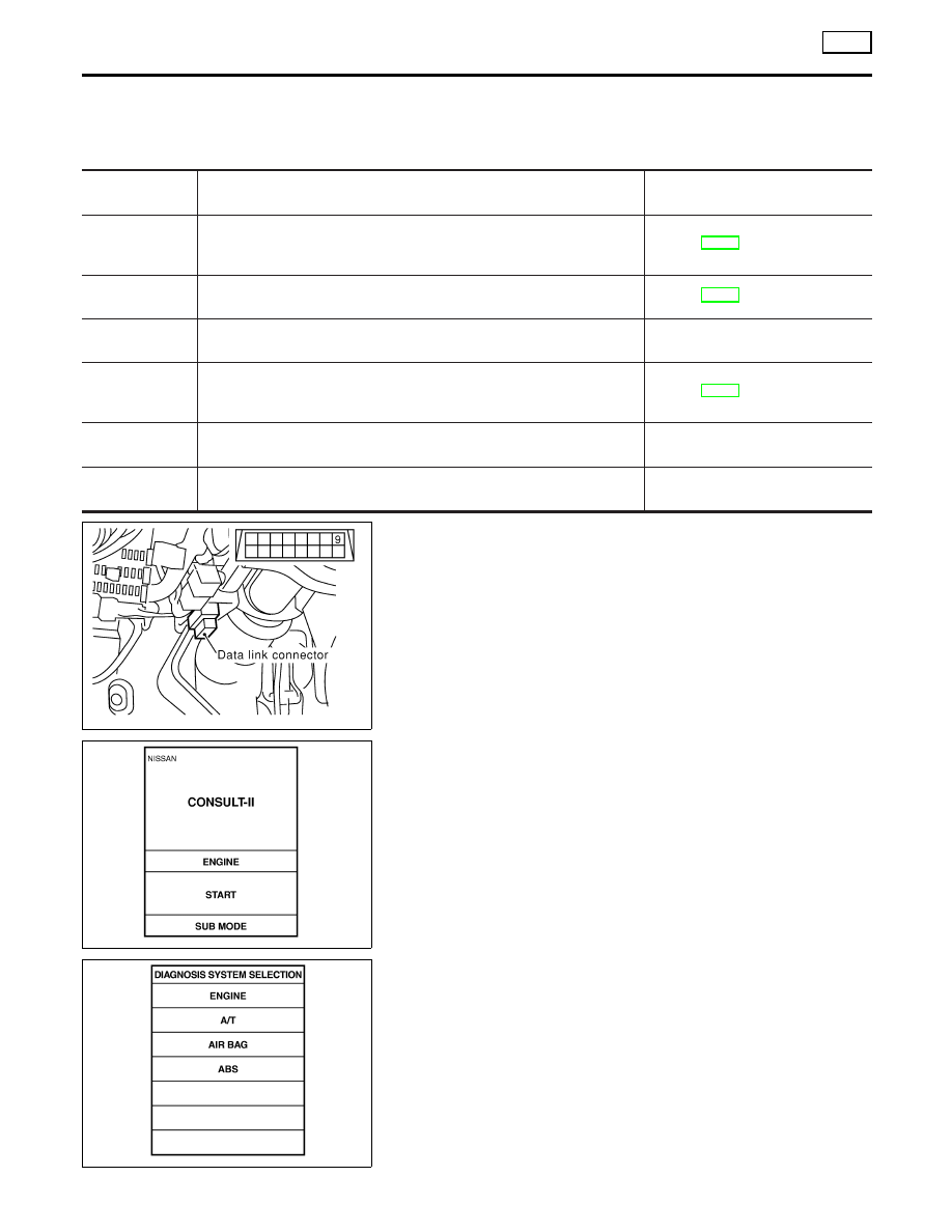
CONSULT-II MAIN FUNCTION
NHBR0151S01
In a diagnosis function (main function), there are “SELF-DIAGNOSTIC RESULTS”, “DATA MONITOR”, “CAN
DIAG SUPPORT MNTR”, “ACTIVE TEST”, “FUNCTION TEST”, “ECU PART NUMBER”.
Diagnostic test
mode
Function
Reference
SELF-DIAG-
NOSTIC
RESULTS
Self-diagnostic results can be read and erased quickly.
Refer to BR-46.
DATA MONITOR
Input/Output data in the ABS actuator and electric unit (control unit) can
be read.
Refer to BR-49.
CAN DIAG SUP-
PORT MNTR
The results of transmit/receive diagnosis of communication can be read.
—
ACTIVE TEST
Diagnostic Test Mode in which CONSULT-II drives some actuators apart
from the ABS actuator and electric unit (control unit) and also shifts some
parameters in a specified range.
Refer to BR-49.
FUNCTION
TEST
Conducted by CONSULT-II instead of a technician to determine whether
each system is “OK” or “NG”.
—
ECU PART
NUMBER
ABS actuator and electric unit (control unit) part number can be read.
—
SBR535E
CONSULT-II Inspection Procedure
NHBR0152
SELF-DIAGNOSIS PROCEDURE
NHBR0152S01
1.
Turn ignition switch OFF.
2.
Connect CONSULT-II to Data Link Connector.
3.
Start engine.
4.
Drive vehicle over 30 km/h (19 MPH) or more for at least one
minute.
SBR905E
5.
Stop vehicle with engine running and touch “START” on CON-
SULT-II screen.
PBR385C
6.
Touch “ABS”.
ON BOARD DIAGNOSTIC SYSTEM DESCRIPTION
TCS
CONSULT-II Functions
BR-46
SFIA2435E
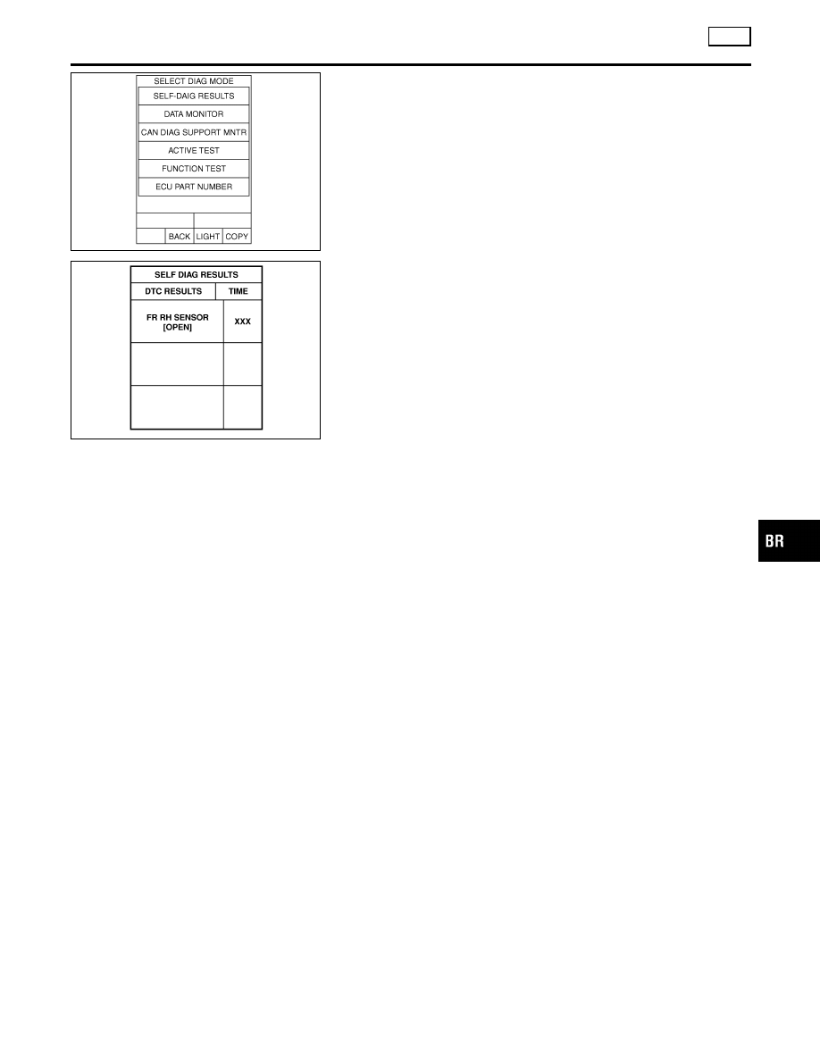
7.
Touch “SELF DIAGNOSIS RESULTS”.
I
The screen shows the detected malfunction and how many
times the ignition switch has been turned since the malfunc-
tion.
8.
Make the necessary repairs following the diagnostic proce-
dures.
SBR561E
9.
After the malfunctions are repaired, erase the self-diagnostic
results stored in the control unit by touching “ERASE”.
10. Check ABS warning lamp, SLIP indicator lamp, TCS OFF indi-
cator lamp for deactivation after driving vehicle over 30 km/h
(19 MPH) or more for at least one minute.
NOTE:
“SELF-DIAG RESULTS” screen shows the detected malfunction
and how many times the ignition switch has been turned since the
malfunction.
GI
MA
EM
LC
EC
FE
AT
AX
SU
ST
RS
BT
HA
SC
EL
IDX
ON BOARD DIAGNOSTIC SYSTEM DESCRIPTION
TCS
CONSULT-II Inspection Procedure (Cont’d)
BR-47
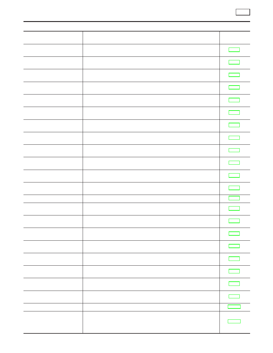
SELF-DIAGNOSTIC RESULTS MODE
=NHBR0152S02
Diagnostic item
Diagnostic item is detected when ...
Reference
Page
FR RH SENSOR-1
I
Circuit for front right wheel sensor is open.
(An abnormally high input voltage is entered.)
FR LH SENSOR-1
I
Circuit for front left wheel sensor is open.
(An abnormally high input voltage is entered.)
RR RH SENSOR-1
I
Circuit for rear right wheel sensor is open.
(An abnormally high input voltage is entered.)
RR LH SENSOR-1
I
Circuit for rear left wheel sensor is open.
(An abnormally high input voltage is entered.)
FR RH SENSOR-2
I
Circuit for front right wheel sensor is shorted.
(An abnormally low input voltage is entered.)
FR LH SENSOR-2
I
Circuit for front left wheel sensor is shorted.
(An abnormally low input voltage is entered.)
RR RH SENSOR-2
I
Circuit for rear right wheel sensor is shorted.
(An abnormally low input voltage is entered.)
RR LH SENSOR-2
I
Circuit for rear left wheel sensor is shorted.
(An abnormally low input voltage is entered.)
ABS SENSOR
[ABNORMAL SIGNAL]
I
Teeth damage on sensor rotor or improper installation of wheel sensor.
(Abnormal wheel sensor signal is entered.)
ABS ACTUATOR RELAY
[ABNORMAL]
I
Actuator solenoid valve relay is ON, even control unit sends off signal.
I
Actuator solenoid valve relay is OFF, even control unit sends on signal.
PUMP MOTOR
I
Circuit for actuator motor is open or shorted.
I
Actuator motor relay is stuck.
BATTERY VOLTAGE
[ABNORMAL]
I
Power source voltage supplied to ABS/TCS control unit is abnormally low or
high.
CONTROLER FAILURE
I
Function of calculation in ABS/TCS control unit has failed.
FR LH IN ABS SOL
I
Circuit of the front LH wheel inlet solenoid valve is open or short, or the
control line is open or short to the power supply or the ground.
FR LH OUT ABS SOL
I
Circuit of the front LH wheel outlet solenoid valve is open or short, or the
control line is open or short to the power supply or the ground.
RR RH IN ABS SOL
I
Circuit of the rear RH wheel inlet solenoid valve is open or short, or the con-
trol line is open or short to the power supply or the ground.
RR RH OUT ABS SOL
I
Circuit of the rear RH wheel outlet solenoid valve is open or short, or the
control line is open or short to the power supply or the ground.
FR RH IN ABS SOL
I
Circuit of the front RH wheel inlet solenoid valve is open or short, or the
control line is open or short to the power supply or the ground.
FR RH OUT ABS SOL
I
Circuit of the front RH wheel outlet solenoid valve is open or short, or the
control line is open or short to the power supply or the ground.
RR LH IN ABS SOL
I
Circuit of the rear LH wheel inlet solenoid valve is open or short, or the con-
trol line is open or short to the power supply or the ground.
RR LH OUT ABS SOL
I
Circuit of the rear LH wheel outlet solenoid valve is open or short, or the
control line is open or short to the power supply or the ground.
ENGINE SIGNAL 1, 2, 3, 4
Engine related part has malfunction.
CAN COMM CIRCUIT*2
I
CAN communication line is open or short.
I
TCS/ABS control unit internal malfunction.
I
Power supply for ECM is interrupted instantane ously for approx. 0.5 sec-
onds or more.
ON BOARD DIAGNOSTIC SYSTEM DESCRIPTION
TCS
CONSULT-II Inspection Procedure (Cont’d)
BR-48
Нет комментариевНе стесняйтесь поделиться с нами вашим ценным мнением.
Текст