Infiniti I35 (A33). Manual — part 313
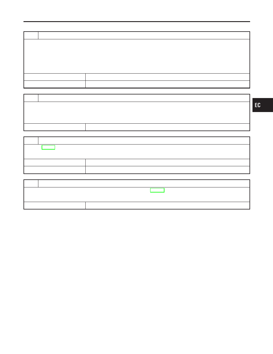
Diagnostic Procedure
=NHEC1115
1
CHECK FUEL LEVEL SENSOR GROUND CIRCUIT FOR OPEN AND SHORT
1. Turn ignition switch OFF.
2. Disconnect ECM harness connector.
3. Check harness continuity between ECM terminal 78 and ground. Refer to Wiring Diagram.
Continuity should exist.
4. Also check harness for short to power.
OK or NG
OK
©
GO TO 3.
NG
©
GO TO 2.
2
DETECT MALFUNCTIONING PART
1. Check the following.
I
Harness connectors F66, M229
I
Harness connectors M110, B43
I
Harness for open between ECM and ground
©
Replace open circuit or short to power in harness or connectors.
3
CHECK FUEL LEVEL SENSOR
Refer to EL-140, “Fuel Level Sensor Unit Check”.
OK or NG
OK
©
GO TO 4.
NG
©
Replace fuel level sensor unit.
4
CHECK INTERMITTENT INCIDENT
Refer to “TROUBLE DIAGNOSIS FOR INTERMITTENT INCIDENT”, EC-152.
OK or NG
©
INSPECTION END
GI
MA
EM
LC
FE
AT
AX
SU
BR
ST
RS
BT
HA
SC
EL
IDX
DTC P1464 FUEL LEVEL SENSOR
Diagnostic Procedure
EC-593
SEF278X
Description
=NHEC1116
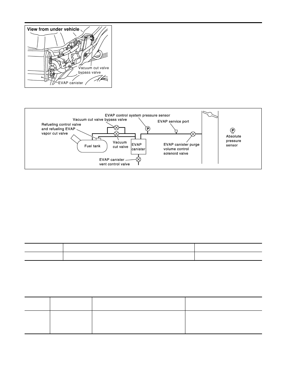
COMPONENT DESCRIPTION
NHEC1116S01
The vacuum cut valve and vacuum cut valve bypass valve are
installed in parallel on the EVAP purge line between the fuel tank
and the EVAP canister.
The vacuum cut valve prevents the intake manifold vacuum from
being applied to the fuel tank.
The vacuum cut valve bypass valve is a solenoid type valve and
generally remains closed. It opens only for on board diagnosis.
The vacuum cut valve bypass valve responds to signals from the
ECM. When the ECM sends an ON (ground) signal, the valve is
opened. The vacuum cut valve is then bypassed to apply intake
manifold vacuum to the fuel tank.
EVAPORATIVE EMISSION SYSTEM DIAGRAM
NHEC1116S02
SEC936C
CONSULT-II Reference Value in Data Monitor
Mode
NHEC1117
Specification data are reference values.
MONITOR ITEM
CONDITION
SPECIFICATION
VC/V BYPASS/V
I
Ignition switch: ON
OFF
On Board Diagnosis Logic
NHEC1119
DTC No.
Trouble diagnosis
name
DTC Detecting Condition
Possible Cause
P1490
1490
Vacuum cut valve
bypass valve circuit
An improper voltage signal is sent to ECM through
vacuum cut valve bypass valve.
I
Harness or connectors
(The vacuum cut valve bypass valve
circuit is open or shorted.)
I
Vacuum cut valve bypass valve
DTC P1490 VACUUM CUT VALVE BYPASS VALVE
Description
EC-594
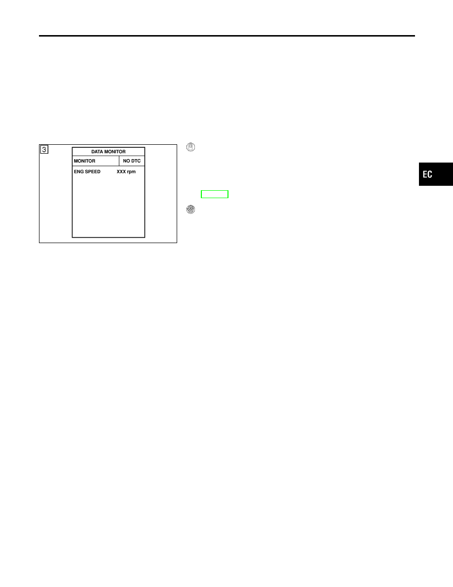
DTC Confirmation Procedure
NHEC1120
NOTE:
If DTC Confirmation Procedure has been previously conducted,
always turn ignition switch OFF and wait at least 10 seconds before
conducting the next test.
TESTING CONDITION:
Before performing the following procedure, confirm that bat-
tery voltage is more than 11V at idle speed.
SEF058Y
WITH CONSULT-II
NHEC1120S01
1)
Turn ignition switch ON.
2)
Select “DATA MONITOR” mode with CONSULT-II.
3)
Start engine and wait at least 5 seconds.
4)
If 1st trip DTC is detected, go to “Diagnostic Procedure”,
EC-597.
WITH GST
NHEC1120S02
Follow the procedure “WITH CONSULT-II” above.
GI
MA
EM
LC
FE
AT
AX
SU
BR
ST
RS
BT
HA
SC
EL
IDX
DTC P1490 VACUUM CUT VALVE BYPASS VALVE
DTC Confirmation Procedure
EC-595
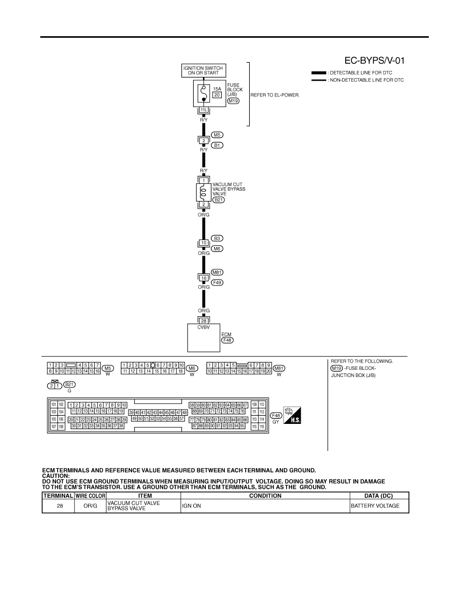
Wiring Diagram
NHEC1121
MEC562D
SEF634XD
DTC P1490 VACUUM CUT VALVE BYPASS VALVE
Wiring Diagram
EC-596
Нет комментариевНе стесняйтесь поделиться с нами вашим ценным мнением.
Текст