Infiniti I35 (A33). Manual — part 299
PBIB0145E
Component Description
NHEC1361
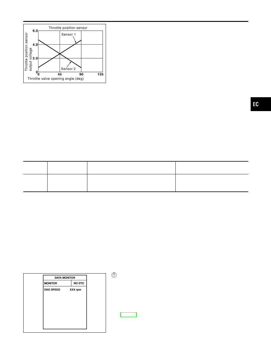
Electric throttle control actuator consists of throttle control motor,
throttle position sensor, etc. The throttle position sensor responds
to the throttle valve movement.
The throttle position sensor has the two sensors. These sensors
are a kind of potentiometers which transform the throttle valve
position into output voltage, and emit the voltage signal to the ECM.
In addition, these sensors detect the opening and closing speed of
the throttle valve and feed the voltage signals to the ECM. The
ECM judges the current opening angle of the throttle valve from
these signals and the ECM controls the throttle control motor to
make the throttle valve opening angle properly in response to driv-
ing condition.
On Board Diagnosis Logic
NHEC1362
The MIL will not light up for this self-diagnosis.
DTC No.
Trouble diagnosis
name
DTC Detecting Condition
Possible Cause
P1226
1226
Closed throttle posi-
tion learning perfor-
mance problem
Closed throttle position learning is not performed
successfully, repeatedly.
I
Electric throttle control actuator (TP
sensor 1 and 2)
DTC Confirmation Procedure
NHEC1363
NOTE:
If DTC Confirmation Procedure has been previously conducted,
always turn ignition switch OFF and wait at least 10 seconds before
conducting the next test.
TESTING CONDITION:
Before performing the following procedure, confirm that bat-
tery voltage is more than 10V at idle.
SEF058Y
With CONSULT-II
1)
Turn ignition switch ON.
2)
Select “DATA MONITOR” mode with CONSULT-II.
3)
Turn ignition switch OFF, wait at least 10 seconds.
4)
Turn ignition switch ON.
5)
Repeat steps 3 and 4, 32 times.
6)
If 1st trip DTC is detected, go to “Diagnostic Procedure”,
EC-538.
GI
MA
EM
LC
FE
AT
AX
SU
BR
ST
RS
BT
HA
SC
EL
IDX
DTC P1226 TP SENSOR
Component Description
EC-537
With GST
Follow the procedure “With CONSULT-II” above.
Diagnostic Procedure
NHEC1364
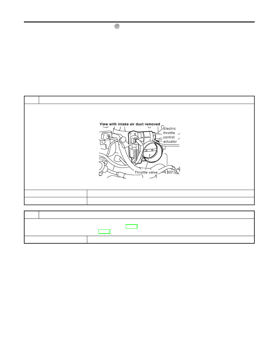
1
CHECK ELECTRIC THROTTLE CONTROL ACTUATOR VISUALLY
1. Turn ignition switch OFF.
2. Remove the intake air duct.
3. Check if foreign matter is caught between the throttle valve and the housing.
SEC083D
OK or NG
OK
©
GO TO 2.
NG
©
Remove the foreign matter and clean the electric throttle control actuator inside.
2
REPLACE ELECTRIC THROTTLE CONTROL ACTUATOR
1. Replace the electric throttle control actuator.
2. Perform “Throttle Valve Closed Position Learning”, EC-70.
3. Perform “Idle Air Volume Learning”, EC-70.
©
INSPECTION END
DTC P1226 TP SENSOR
DTC Confirmation Procedure (Cont’d)
EC-538
On Board Diagnosis Logic
NHEC1460
This self-diagnosis has the one trip detection logic.
DTC No.
Trouble diagnosis
name
DTC Detecting Condition
Possible Cause
P1229
1229
Sensor power supply
circuit short
ECM detects a voltage of power source for sensor
is excessively low or high.
I
Harness or connectors
(The TP sensor 1 and 2 circuit is
shorted.)
(APP sensor circuit is shorted.)
(MAF sensor circuit is shorted.)
(EVAP control system pressure sen-
sor circuit is shorted.)
(Power steering pressure sensor cir-
cuit is shorted.)
(Refrigerant pressure sensor circuit is
shorted.)
I
Electric throttle control actuator
(TP sensor 1 and 2)
I
Accelerator pedal position sensor
(APP sensor 1)
I
MAF sensor
I
EVAP control system pressure sensor
I
Power steering pressure sensor
I
Refrigerant pressure sensor
I
ECM pin terminal
FAIL-SAFE MODE
NHEC1460S01
When the malfunction is detected, ECM enters fail-safe mode and the MIL lights up.
Engine operation condition in fail-safe mode
ECM stops the electric throttle control actuator control, throttle valve is maintained at a fixed opening (approx. 5 degrees) by the
return spring.
DTC Confirmation Procedure
NHEC1461
NOTE:
If DTC Confirmation Procedure has been previously conducted,
always turn ignition switch OFF and wait at least 10 seconds before
conducting the next test.
TESTING CONDITION:
Before performing the following procedure, confirm that bat-
tery voltage is more than 10V at idle.
SEF058Y
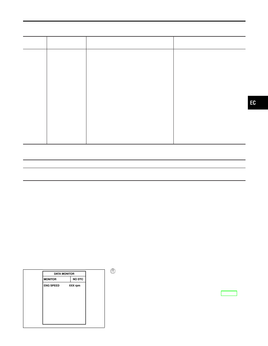
With CONSULT-II
1)
Turn ignition switch ON.
2)
Select “DATA MONITOR” mode with CONSULT-II.
3)
Start engine and let it idle for 1 second.
4)
If DTC is detected, go to “Diagnostic Procedure”, EC-542.
GI
MA
EM
LC
FE
AT
AX
SU
BR
ST
RS
BT
HA
SC
EL
IDX
DTC P1229 SENSOR POWER SUPPLY
On Board Diagnosis Logic
EC-539
With GST
Follow the procedure “With CONSULT-II” above.
DTC P1229 SENSOR POWER SUPPLY
DTC Confirmation Procedure (Cont’d)
EC-540
Нет комментариевНе стесняйтесь поделиться с нами вашим ценным мнением.
Текст