Infiniti I35 (A33). Manual — part 530
MHA077A
GI
MA
EM
LC
EC
FE
AT
AX
SU
BR
ST
RS
BT
SC
EL
IDX
TROUBLE DIAGNOSES
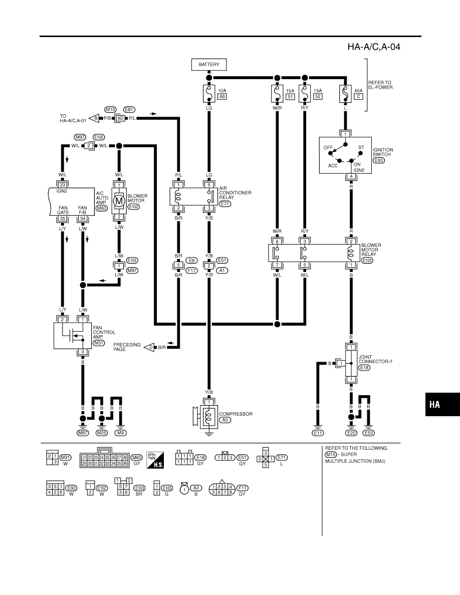
Wiring Diagram — A/C, A — (Cont’d)
HA-33
RHA036IA
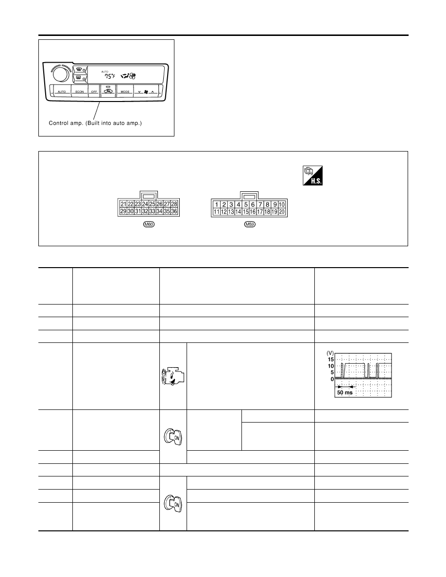
Auto Amp. Terminals and Reference Value
NHHA0175
INSPECTION OF AUTO AMP.
NHHA0175S01
I
Measure voltage between each terminal and body ground by
following “AUTO AMP. INSPECTION TABLE”.
I
Pin connector terminal layout
RHA501GC
AUTO AMP. INSPECTION TABLE
NHHA0175S02
TERMI-
NAL NO.
(Wire
color)
ITEM
CONDITION
Voltage
V
1 (R/W)
Intake sensor
—
—
2 (OR/B)
Ambient sensor
—
—
3 (OR/L)
In-vehicle sensor
—
—
5 (PU/W)
Engine coolant temperature
sensor
At idle [after warming up, approx. 80°C
(176°F)]
NOTE:
The waveforms vary depending on coolant
temperature.
SHA606F
8 (PU)
Compressor feed back signal
AUTO SW: ON
—
Approximately 0
When refrigerant pres-
sure sensor connector is
disconnected
Approximately 5
11 (B)
Sensor ground
—
Approximately 0
12 (OR)
Sunload sensor
—
—
14 (B)
Ground (for Canada)
—
Approximately 0
16 (L/B)
A/C LAN signal
—
—
21 (L/W)
Power supply for air mix door
motor, mode door motor and
intake door motor
—
Approximately 12
TROUBLE DIAGNOSES
Auto Amp. Terminals and Reference Value
HA-34
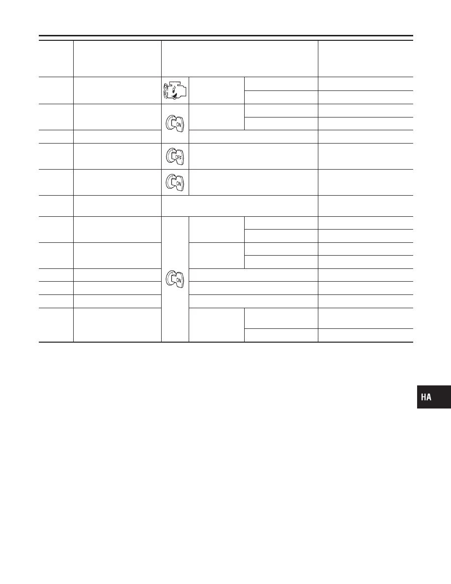
TERMI-
NAL NO.
(Wire
color)
ITEM
CONDITION
Voltage
V
22 (G/B)
Compressor ON signal
Compressor
ON
Approximately 0
OFF
Approximately 5
24 (R/W)
Power supply for illumination
Lighting switch
OFF
Approximately 0
1st
Approximately 12
25 (R/Y)
Illumination ground
—
Approximately 0
26 (Y/R)
Power supply for BAT
—
BATTERY VOLTAGE
27 (P/B)
Power supply for IGN
—
Approximately 12
28 (SB)
Ambient temperature output
signal
—
—
30 (G)
Rear window defogger feed
back
Rear window
defogger switch
ON
Approximately 12
OFF
Approximately 0
31 (G/W)
Rear window defogger ON
signal
Rear window
defogger switch
ON
Approximately 0
OFF
Approximately 12
32 (B)
Ground
—
Approximately 0
33 (W/L)
Power source for IGN2
Ignition voltage feedback
Approximately 12
34 (L/W)
Feedback signal
Fan speed: Low
Approximately 7 - 10
35 (L/Y)
Fan control AMP. control sig-
nal
Fan speed
Low, Middle low or
Middle high
Approximately 2.5 - 3.0
High
Approximately 9 - 10
GI
MA
EM
LC
EC
FE
AT
AX
SU
BR
ST
RS
BT
SC
EL
IDX
TROUBLE DIAGNOSES
Auto Amp. Terminals and Reference Value (Cont’d)
HA-35
Self-diagnosis
=NHHA0176
INTRODUCTION AND GENERAL DESCRIPTION
NHHA0176S01
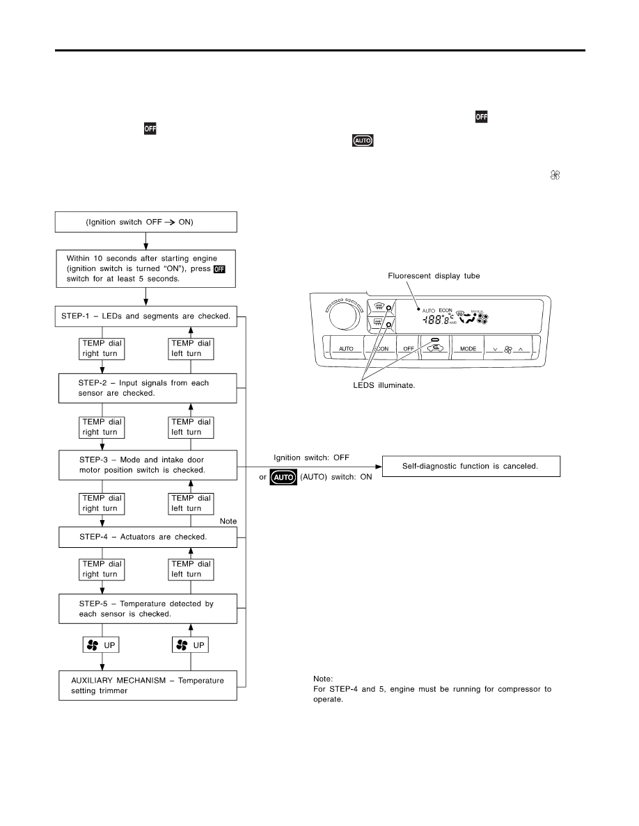
The self-diagnostic system diagnoses sensors, door motors, blower motor, etc. by system line. Refer to appli-
cable sections (items) for details. Shifting from normal control to the self-diagnostic system is accomplished
by starting the engine (turning the ignition switch from “OFF” to “ON”) and pressing “
” switch for at least
5 seconds. The “
” switch must be pressed within 5 seconds after starting the engine (ignition switch is
turned “ON”). This system will be canceled by either pressing
(AUTO) switch or turning the ignition switch
“OFF”. Shifting from one step to another is accomplished by means of turning TEMP dial clockwise or
counterclockwise, as required.
Additionally shifting from STEP 5 to AUXILIARY MECHANISM is accomplished by means of pushing
(fan)
UP switch.
RHA092IA
Perform all of the following tests to narrow the problem to a specific assembly, actuator, or function.
Link to the diagnostic procedure which corresponds to malfunctions noted in these tests.
If the A/C display screen has no display, check all power supply circuits to the A/C auto amp.
TROUBLE DIAGNOSES
Self-diagnosis
HA-36
Нет комментариевНе стесняйтесь поделиться с нами вашим ценным мнением.
Текст