Infiniti I35 (A33). Manual — part 223

5
CHECK HEATED OXYGEN SENSOR 1
With CONSULT-II
1. Start engine and warm it up to normal operating temperature.
2. Select “MANU TRIG” and adjust “TRIGGER POINT” to 100% in “DATA MONITOR” mode with CONSULT-II.
3. Select “HO2S1 (B1)/(B2)” and “HO2S1 MNTR (B1)/(B2)”.
4. Hold engine speed at 2,000 rpm under no load during the following steps.
5. Touch “RECORD” on CONSULT-II screen.
SEF967Y
6. Check the following.
I
“HO2S1 MNTR (B1)/(B2)” in “DATA MONITOR” mode changes from “RICH” to “LEAN” to “RICH” more than 5 times in
10 seconds.
5 times (cycles) are counted as shown left:
SEF647Y
I
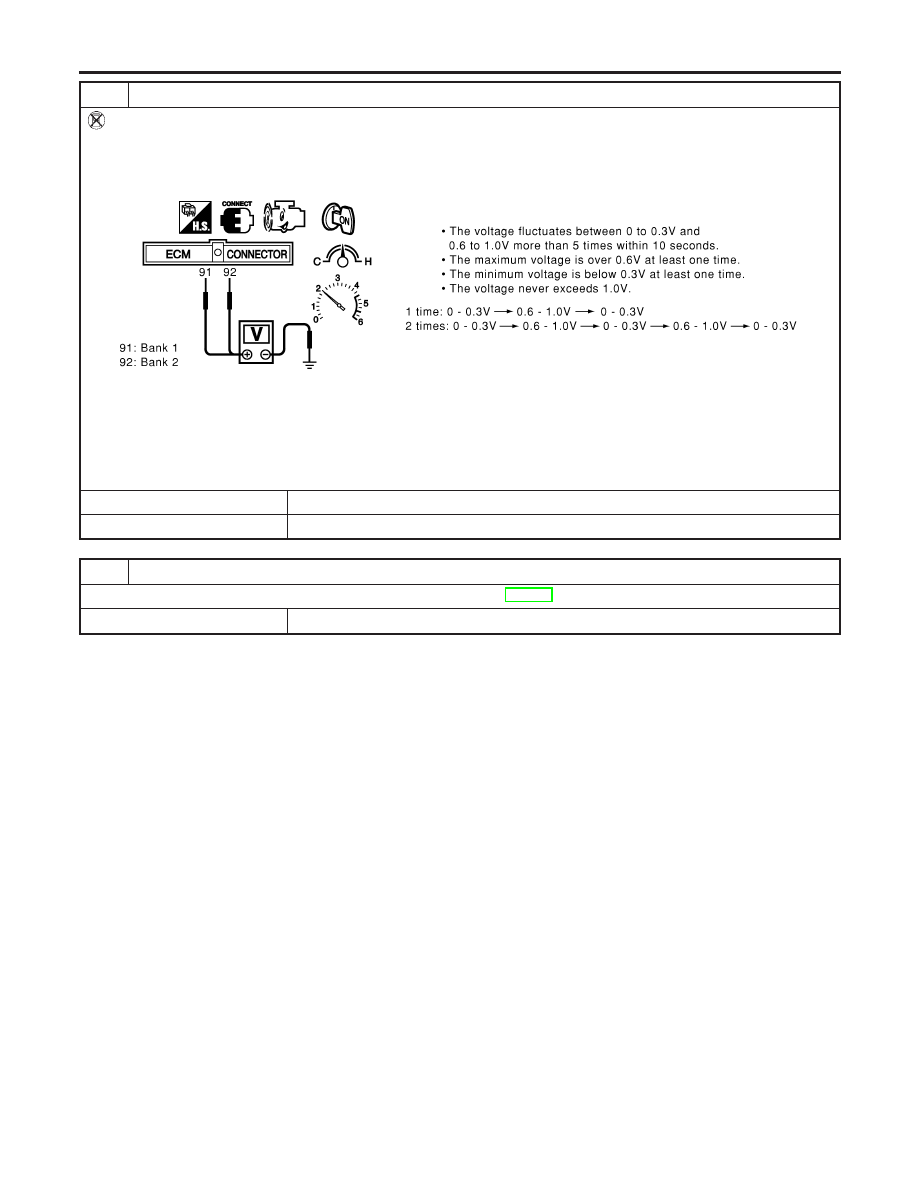
“HO2S1 (B1)/(B2)” voltage goes above 0.6V at least once.
I
“HO2S1 (B1)/(B2)” voltage goes below 0.3V at least once.
I
“HO2S1 (B1)/(B2)” voltage never exceeds 1.0V.
SEF648Y
CAUTION:
I
Discard any heated oxygen sensor which has been dropped from a height of more than 0.5 m (19.7 in) onto a
hard surface such as a concrete floor; use a new one.
I
Before installing new oxygen sensor, clean exhaust system threads using Oxygen Sensor Thread Cleaner tool
J-43897-18 or J-43897-12 and approved anti-seize lubricant.
OK or NG
OK
©
GO TO 7.
NG
©
Replace malfunctioning heated oxygen sensor 1.
GI
MA
EM
LC
FE
AT
AX
SU
BR
ST
RS
BT
HA
SC
EL
IDX
DTC P0132, P0152 HO2S1
Diagnostic Procedure (Cont’d)
EC-233
6
CHECK HEATED OXYGEN SENSOR 1
Without CONSULT-II
1. Start engine and warm it up to normal operating temperature.
2. Set voltmeter probes between ECM terminal 91 (HO2S1 bank 1 signal) or 92 (HO2S1 bank 2 signal) and ground.
3. Check the following with engine speed held at 2,000 rpm constant under no load.
SEC109D
CAUTION:
I
Discard any heated oxygen sensor which has been dropped from a height of more than 0.5 m (19.7 in) onto a
hard surface such as a concrete floor; use a new one.
I
Before installing new oxygen sensor, clean exhaust system threads using Oxygen Sensor Thread Cleaner tool
J-43897-18 or J-43897-12 and approved anti-seize lubricant.
OK or NG
OK
©
GO TO 7.
NG
©
Replace malfunctioning heated oxygen sensor 1.
7
CHECK INTERMITTENT INCIDENT
Refer to “TROUBLE DIAGNOSIS FOR INTERMITTENT INCIDENT”, EC-152.
©
INSPECTION END
DTC P0132, P0152 HO2S1
Diagnostic Procedure (Cont’d)
EC-234

SEF463R
SEF288D
Component Description
NHEC0880
The heated oxygen sensor 1 is placed into the front tube. It detects
the amount of oxygen in the exhaust gas compared to the outside
air. The heated oxygen sensor 1 has a closed-end tube made of
ceramic zirconia. The zirconia generates voltage from approxi-
mately 1V in richer conditions to 0V in leaner conditions. The
heated oxygen sensor 1 signal is sent to the ECM. The ECM
adjusts the injection pulse duration to achieve the ideal air-fuel
ratio. The ideal air-fuel ratio occurs near the radical change from
1V to 0V.
CONSULT-II Reference Value in Data Monitor
Mode
NHEC0881
Specification data are reference values.
MONITOR ITEM
CONDITION
SPECIFICATION
HO2S1 (B1)
HO2S1 (B2)
I
Engine: After warming up
Maintaining engine speed at 2,000
rpm
0 - 0.3V
+,
Approx. 0.6 - 1.0V
HO2S1 MNTR
(B1)
HO2S1 MNTR
(B2)
LEAN
+,
RICH
Changes more than 5 times during
10 seconds.
SEF010V
On Board Diagnosis Logic
NHEC0883
To judge the malfunction of heated oxygen sensor 1, this diagno-
sis measures response time of heated oxygen sensor 1 signal. The
time is compensated by engine operating (speed and load), fuel
feedback control constant, and heated oxygen sensor 1 tempera-
ture index. Judgment is based on whether the compensated time
[heated oxygen sensor 1 cycling time index] is inordinately long or
not.
GI
MA
EM
LC
FE
AT
AX
SU
BR
ST
RS
BT
HA
SC
EL
IDX
DTC P0133, P0153 HO2S1
Component Description
EC-235

DTC No.
Trouble diagnosis
name
DTC Detecting Condition
Possible Cause
P0133
0133
(Bank 1)
P0153
0153
(Bank 2)
Heated oxygen sen-
sor 1 circuit slow
response
The response of the voltage signal from the sen-
sor takes more than the specified time.
I
Harness or connectors
(The sensor circuit is open or
shorted.)
I
Heated oxygen sensor 1
I
Heated oxygen sensor 1 heater
I
Fuel pressure
I
Injector
I
Intake air leaks
I
Exhaust gas leaks
I
PCV valve
I
Mass air flow sensor
DTC Confirmation Procedure
NHEC0884
CAUTION:
Always drive vehicle at a safe speed.
NOTE:
If DTC Confirmation Procedure has been previously conducted,
always turn ignition switch OFF and wait at least 10 seconds before
conducting the next test.
TESTING CONDITION:
I
Always perform at a temperature above −10°C (14°F).
I
Before performing the following procedure, confirm that
battery voltage is more than 11V at idle.
DTC P0133, P0153 HO2S1
On Board Diagnosis Logic (Cont’d)
EC-236
Нет комментариевНе стесняйтесь поделиться с нами вашим ценным мнением.
Текст