Infiniti I35 (A33). Manual — part 270
Diagnostic Procedure
=NHEC0995
1
CHECK FUEL LEVEL SENSOR POWER SUPPLY CIRCUIT
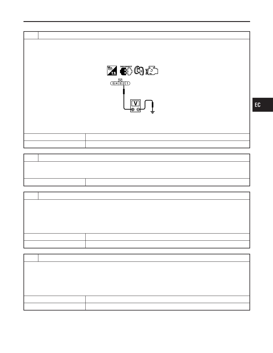
1. Turn ignition switch OFF.
2. Disconnect “fuel level sensor unit and fuel pump” harness connector.
3. Turn ignition switch ON.
4. Check voltage between “fuel level sensor unit and fuel pump” terminal 2 and ground with CONSULT-II or a tester.
SEC065D
Voltage: Battery voltage
OK or NG
OK
©
GO TO 3.
NG
©
GO TO 2.
2
DETECT MALFUNCTIONING PART
Check the following.
I
Harness connectors M6, B3
I
Harness for open or short between combination meter and “fuel level sensor unit and fuel pump”
©
Repair or replace harness or connectors.
3
CHECK FUEL LEVEL SENSOR GROUND CIRCUIT FOR OPEN AND SHORT
1. Turn ignition switch OFF.
2. Check harness continuity between “fuel level sensor unit and fuel pump” terminal 5 and ground. Refer to Wiring Dia-
gram.
Continuity should exist.
3. Also check harness for short to power.
OK or NG
OK
©
GO TO 4.
NG
©
Repair open circuit or short to power in harness or connectors.
4
CHECK FUEL LEVEL SENSOR INPUT SIGNAL CIRCUIT FOR OPEN AND SHORT
1. Disconnect ECM harness connector.
2. Check harness continuity between ECM terminal 69 and “fuel level sensor unit and fuel pump” terminal 2, ECM termi-
nal 78 and “fuel level sensor unit and fuel pump” terminal 5. Refer to Wiring Diagram.
Continuity should exist.
3. Also check harness for short to ground and short to power.
OK or NG
OK
©
GO TO 6.
NG
©
GO TO 5.
GI
MA
EM
LC
FE
AT
AX
SU
BR
ST
RS
BT
HA
SC
EL
IDX
DTC P0460 FUEL LEVEL SENSOR
Diagnostic Procedure
EC-421
5
DETECT MALFUNCTIONING PART
Check the following.
I
Harness connectors M229, F66
I
Harness connectors M6, B3
I
Harness for open or short between ECM and “fuel level sensor unit and fuel pump”
©
Repair open circuit or short to ground or short to power in harness or connectors.
6
CHECK FUEL LEVEL SENSOR
Refer to EL-140, “Fuel Level Sensor Unit Check”.
OK or NG
OK
©
GO TO 7.
NG
©
Replace fuel level sensor unit and fuel pump.
7
CHECK INTERMITTENT INCIDENT
Refer to “TROUBLE DIAGNOSIS FOR INTERMITTENT INCIDENT”, EC-152.
©
INSPECTION END
DTC P0460 FUEL LEVEL SENSOR
Diagnostic Procedure (Cont’d)
EC-422
SEC088D
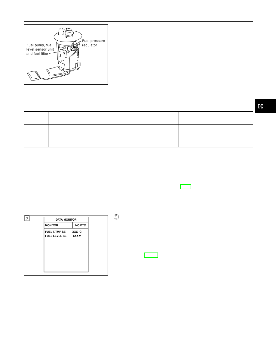
Component Description
=NHEC0996
The fuel level sensor is mounted in the fuel level sensor unit. The
sensor detects a fuel level in the fuel tank and transmits a signal
to the ECM.
It consists of two parts, one is mechanical float and the other is
variable resistor. Fuel level sensor output voltage changes depend-
ing on the movement of the fuel mechanical float.
On Board Diagnostic Logic
NHEC0997
Driving long distances naturally affect fuel gauge level.
This diagnosis detects the fuel gauge malfunction of the gauge not
moving even after a long distance has been driven.
DTC No.
Trouble diagnosis
name
DTC Detecting Condition
Possible Cause
P0461
0461
Fuel level sensor cir-
cuit range/
performance
The output signal of the fuel level sensor does not
change within the specified range even though the
vehicle has been driven a long distance.
I
Harness or connectors
(The level sensor circuit is open or
shorted.)
I
Fuel level sensor
Overall Function Check
NHEC0998
Use this procedure to check the overall function of the fuel level
sensor function. During this check, a 1st trip DTC might not be
confirmed.
WARNING:
When performing following procedure, be sure to observe the
handling of the fuel. Refer to FE-4, “Fuel Tank”.
TESTING CONDITION:
Before starting overall function check, preparation of draining
fuel and refilling fuel is required.
SEF195Y
WITH CONSULT-II
NHEC0998S01
NOTE:
Start from step 11, if it is possible to confirm that the fuel
cannot be drained by 30
(7-7/8 US gal, 6-5/8 Imp gal) in
advance.
1)
Prepare a fuel container and a spare hose.
2)
Release fuel pressure from fuel line, refer to “Fuel Pressure
Release”, EC-55.
3)
Remove the fuel feed hose on the fuel level sensor unit.
4)
Connect a spare fuel hose where the fuel feed hose was
removed.
5)
Turn ignition switch OFF and wait at least 10 seconds then turn
ON.
6)
Select “FUEL LEVEL SE” in “DATA MONITOR” mode with
CONSULT-II.
7)
Check “FUEL LEVEL SE” output voltage and note it.
8)
Select “FUEL PUMP” in “ACTIVE TEST” mode with CON-
SULT-II.
9)
Touch ON and drain fuel approximately 30
(7-7/8 US gal,
6-5/8 Imp gal) and stop it.
10) Fill fuel into the fuel tank for 30
(7-7/8 US gal, 6-5/8 Imp gal).
11) Check “FUEL LEVEL SE” output voltage and note it.
GI
MA
EM
LC
FE
AT
AX
SU
BR
ST
RS
BT
HA
SC
EL
IDX
DTC P0461 FUEL LEVEL SENSOR
Component Description
EC-423
12) Check “FUEL LEVEL SE” output voltage and confirm whether
the voltage changes more than 0.03V during step 7 to 11.
If NG, check the fuel level sensor, refer to EL-140, “FUEL
LEVEL SENSOR UNIT CHECK”.
SEC910C
WITH GST
NHEC0998S02
NOTE:
Start from step 11, if it is possible to confirm that the fuel
cannot be drained by 30
(7-7/8 US gal, 6-5/8 Imp gal) in
advance.
1)
Prepare a fuel container and a spare hose.
2)
Release fuel pressure from fuel line, refer to “Fuel Pressure
Release”, EC-55.
3)
Remove the fuel feed hose on the fuel level sensor unit.
4)
Connect a spare fuel hose where the fuel feed hose was
removed.
5)
Turn ignition switch OFF.
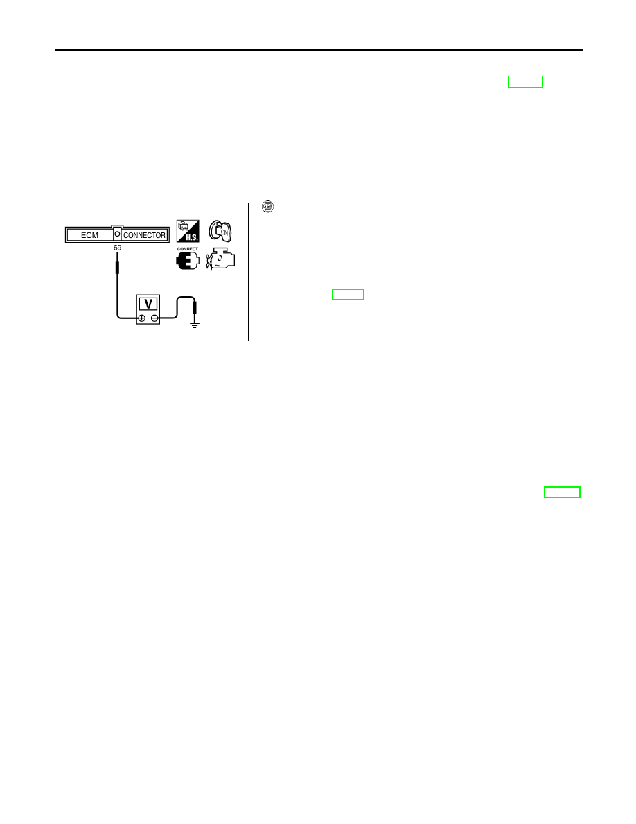
6)
Set voltmeters probe between ECM terminal 69 (fuel level
sensor signal) and ground.
7)
Turn ignition switch ON.
8)
Check voltage between ECM terminal 69 and ground and note
it.
9)
Drain fuel by 30
(7-7/8 US gal, 6-5/8 Imp gal) from the fuel
tank using proper equipment.
10) Fill fuel into the fuel tank for 30
(7-7/8 US gal, 6-5/8 Imp gal).
11) Confirm that the voltage between ECM terminal 69 and ground
changes more than 0.03V during step 8 - 10.
If NG, check component of fuel level sensor, refer to EL-140,
“FUEL LEVEL SENSOR UNIT CHECK”.
DTC P0461 FUEL LEVEL SENSOR
Overall Function Check (Cont’d)
EC-424
Нет комментариевНе стесняйтесь поделиться с нами вашим ценным мнением.
Текст