Infiniti I35 (A33). Manual — part 515
4)
With SW1 closed, relay and solenoid disconnected and the
DMM leads across both fuse terminals, check for voltage.
voltage; short is between SW1 and the relay (point B).
no voltage; short is further down the circuit than the relay.
5)
With SW1 closed, relay contacts jumped with fused jumper
wire check for voltage.
voltage; short is down the circuit of the relay or between the
relay and the disconnected solenoid (point C).
no voltage; retrace steps and check power to fuse block.
GROUND INSPECTION
NHGI0005S0304
Ground connections are very important to the proper operation of
electrical and electronic circuits. Ground connections are often
exposed to moisture, dirt and other corrosive elements. The corro-
sion (rust) can become an unwanted resistance. This unwanted
resistance can change the way a circuit works.
Electronically controlled circuits are very sensitive to proper
grounding. A loose or corroded ground can drastically affect an
electronically controlled circuit. A poor or corroded ground can eas-
ily affect the circuit. Even when the ground connection looks clean,
there can be a thin film of rust on the surface.
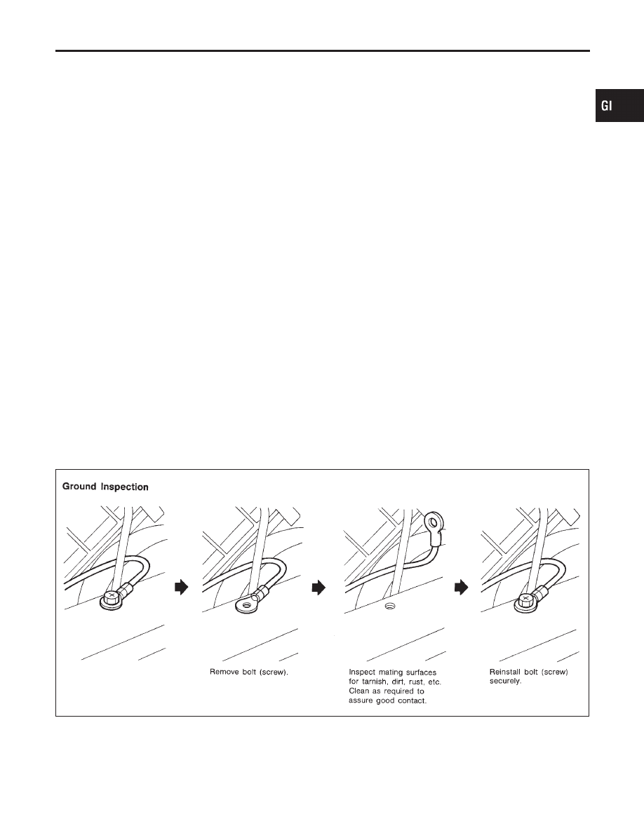
When inspecting a ground connection follow these rules:
1)
Remove the ground bolt or screw.
2)
Inspect all mating surfaces for tarnish, dirt, rust, etc.
3)
Clean as required to assure good contact.
4)
Reinstall bolt or screw securely.
5)
Inspect for “add-on” accessories which may be interfering with
the ground circuit.
6)
If several wires are crimped into one ground eyelet terminal,
check for proper crimps. Make sure all of the wires are clean,
securely fastened and providing a good ground path. If multiple
wires are cased in one eyelet make sure no ground wires have
excess wire insulation.
SGI853
VOLTAGE DROP TESTS
NHGI0005S0305
Voltage drop tests are often used to find components or circuits
which have excessive resistance. A voltage drop in a circuit is
caused by a resistance when the circuit is in operation.
Check the wire in the illustration. When measuring resistance with
MA
EM
LC
EC
FE
AT
AX
SU
BR
ST
RS
BT
HA
SC
EL
IDX
HOW TO PERFORM EFFICIENT DIAGNOSIS FOR AN ELECTRICAL INCIDENT
Circuit Inspection (Cont’d)
GI-31
ohmmeter, contact by a single strand of wire will give reading of 0
ohms. This would indicate a good circuit. When the circuit operates,
this single strand of wire is not able to carry the current. The single
strand will have a high resistance to the current. This will be picked
up as a slight voltage drop.
Unwanted resistance can be caused by many situations as follows:
I
Undersized wiring (single strand example)
I
Corrosion on switch contacts
I
Loose wire connections or splices.
If repairs are needed always use wire that is of the same or larger
gauge.
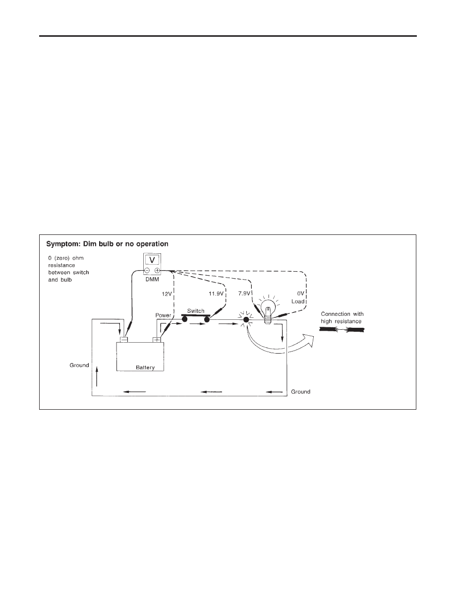
Measuring Voltage Drop — Accumulated Method
1)
Connect the voltmeter across the connector or part of the cir-
cuit you want to check. The positive lead of the voltmeter
should be closer to power and the negative lead closer to
ground.
2)
Operate the circuit.
3)
The voltmeter will indicate how many volts are being used to
“push” current through that part of the circuit.
Note in the illustration that there is an excessive 4.1 volt drop
between the battery and the bulb.
SGI974
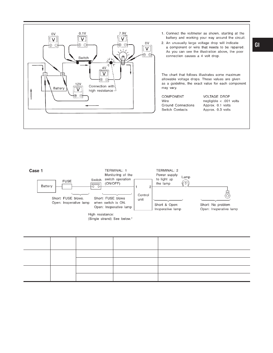
Measuring Voltage Drop — Step by Step
The step by step method is most useful for isolating excessive
drops in low voltage systems (such as those in “Computer Con-
trolled Systems”).
Circuits in the “Computer Controlled System” operate on very low
amperage.
The (Computer Controlled) system operations can be adversely
affected by any variation in resistance in the system. Such resis-
tance variation may be caused by poor connection, improper
installation, improper wire gauge or corrosion.
The step by step voltage drop test can identify a component or wire
with too much resistance.
HOW TO PERFORM EFFICIENT DIAGNOSIS FOR AN ELECTRICAL INCIDENT
Circuit Inspection (Cont’d)
GI-32
SGI854
CONTROL UNIT CIRCUIT TEST
NHGI0005S0306
System Description: When the switch is ON, the control unit lights
up the lamp.
MGI034A
Input-output voltage chart
Pin No.
Item
Condition
Voltage
value [V]
In case of high resistance such as single strand [V]
*
1
Switch
Switch ON
Battery voltage
Lower than battery voltage Approx. 8 (Example)
Switch OFF
Approx. 0
Approx. 0
2
Lamp
Switch ON
Battery voltage
Approx. 0 (Inoperative lamp)
Switch OFF
Approx. 0
Approx. 0
The voltage value is based on the body ground.
* : If high resistance exists in the switch side circuit (caused by a single strand), terminal 1 does not detect battery voltage. Control unit
does not detect the switch is ON even if the switch does not turn ON. Therefore, the control unit does not supply power to light up the
lamp.
MA
EM
LC
EC
FE
AT
AX
SU
BR
ST
RS
BT
HA
SC
EL
IDX
HOW TO PERFORM EFFICIENT DIAGNOSIS FOR AN ELECTRICAL INCIDENT
Circuit Inspection (Cont’d)
GI-33
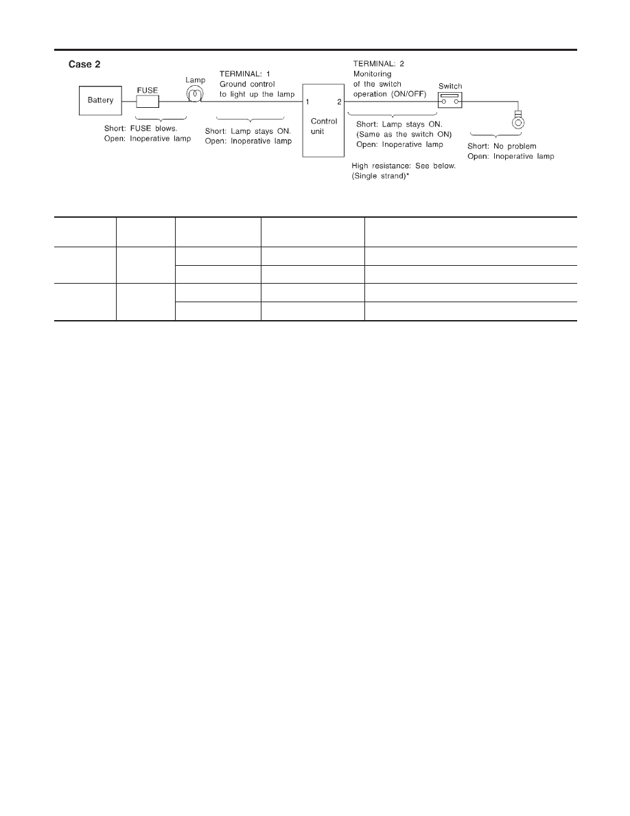
MGI035A
Input-output voltage chart
Pin No.
Item
Condition
Voltage
value [V]
In case of high resistance such as single strand [V]
*
1
Lamp
Switch ON
Approx. 0
Battery voltage (Inoperative lamp)
Switch OFF
Battery voltage
Battery voltage
2
Switch
Switch ON
Approx. 0
Higher than 0 Approx. 4 (Example)
Switch OFF
Approx. 5
Approx. 5
The voltage value is based on the body ground.
* : If high resistance exists in the switch side circuit (caused by a single strand), terminal 2 does not detect approx. 0V. Control unit
does not detect the switch is ON even if the switch does not turn ON. Therefore, the control unit does not control ground to light up the
lamp.
HOW TO PERFORM EFFICIENT DIAGNOSIS FOR AN ELECTRICAL INCIDENT
Circuit Inspection (Cont’d)
GI-34
Нет комментариевНе стесняйтесь поделиться с нами вашим ценным мнением.
Текст