Infiniti I35 (A33). Manual — part 174
I
When engine speed is excessively low.
I
When refrigerant pressure is excessively low or high.
Fuel Cut Control (at no load & high engine
speed)
DESCRIPTION
NHEC0017
Input/Output Signal Chart
NHEC0017S01
Sensor
Input Signal to ECM
ECM func-
tion
Actuator
Vehicle speed (From combination meter)
Vehicle speed
Fuel cut
control
Injectors
Park/neutral position (PNP) switch
Neutral position
Engine coolant temperature sensor
Engine coolant temperature
Crankshaft position sensor (POS)
Engine speed
If the engine speed is above 1,800 rpm under no load (for example, the shift position is neutral and engine
speed is over 1,800 rpm) fuel will be cut off after some time. The exact time when the fuel is cut off varies
based on engine speed.
Fuel cut will be operated until the engine speed reaches 1,500 rpm, then fuel cut is cancelled.
NOTE:
This function is different from deceleration control listed under “Multiport Fuel Injection (MFI) System”, EC-33.
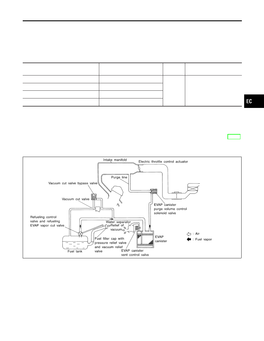
Evaporative Emission System
DESCRIPTION
NHEC0018
SEF569XC
The evaporative emission system is used to reduce hydrocarbons emitted into the atmosphere from the fuel
system. This reduction of hydrocarbons is accomplished by activated charcoals in the EVAP canister.
The fuel vapor in the sealed fuel tank is led into the EVAP canister which contains activated carbon and the
vapor is stored there when the engine is not operating or when refueling to the fuel tank.
The vapor in the EVAP canister is purged by the air through the purge line to the intake manifold when the
engine is operating. EVAP canister purge volume control solenoid valve is controlled by ECM. When the engine
operates, the flow rate of vapor controlled by EVAP canister purge volume control solenoid valve is propor-
tionally regulated as the air flow increases.
EVAP canister purge volume control solenoid valve also shuts off the vapor purge line during decelerating and
idling.
GI
MA
EM
LC
FE
AT
AX
SU
BR
ST
RS
BT
HA
SC
EL
IDX
ENGINE AND EMISSION BASIC CONTROL SYSTEM DESCRIPTION
Air Conditioning Cut Control (Cont’d)
EC-37
SEF396T
INSPECTION
NHEC0019
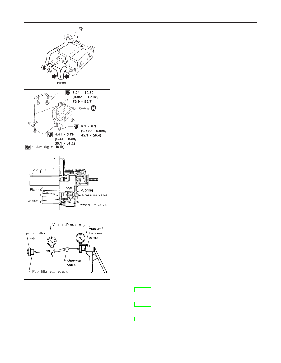
EVAP Canister
NHEC0019S01
Check EVAP canister as follows:
1.
Pinch the fresh air hose.
2.
Blow air into port A and check that it flows freely out of port B.
SEF397T
Tightening Torque
NHEC0019S02
Tighten EVAP canister as shown in the figure.
Make sure new O-ring is installed properly between EVAP can-
ister and EVAP canister vent control valve.
SEF445Y
SEF943S
Fuel Tank Vacuum Relief Valve (Built into fuel filler cap)
NHEC0019S03
1.
Wipe clean valve housing.
2.
Check valve opening pressure and vacuum.
Pressure:
15.3 - 20.0 kPa (0.156 - 0.204 kg/cm
2
, 2.22 - 2.90 psi)
Vacuum:
−6.0 to −3.3 kPa (−0.061 to −0.034 kg/cm
2
, −0.87 to
−0.48 psi)
3.
If out of specification, replace fuel filler cap as an assembly.
CAUTION:
Use only a genuine fuel filler cap as a replacement. If an incor-
rect fuel filler cap is used, the MIL may come on.
Vacuum Cut Valve and Vacuum Cut Valve Bypass Valve
NHEC0019S04
Refer to EC-600.
EVAP Canister Purge Volume Control Solenoid Valve
NHEC0019S05
Refer to EC-362.
Fuel Tank Temperature Sensor
NHEC0019S06
Refer to EC-291.
ENGINE AND EMISSION BASIC CONTROL SYSTEM DESCRIPTION
Evaporative Emission System (Cont’d)
EC-38
SEF462UA
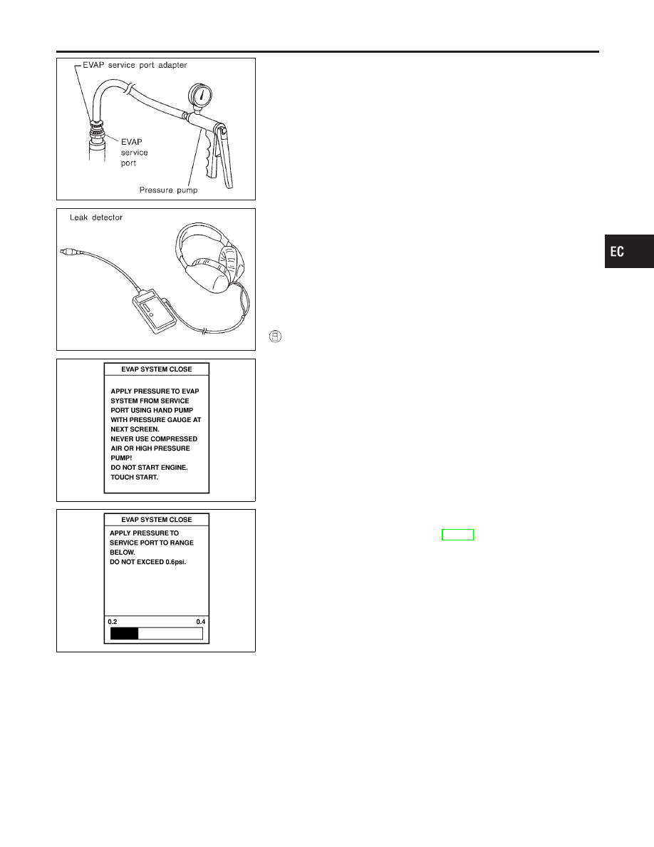
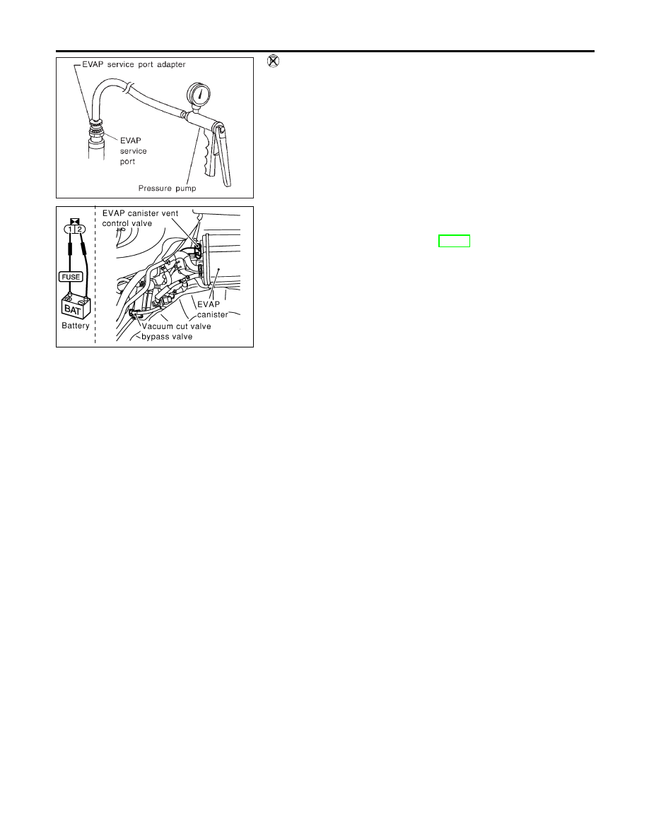
EVAP Service Port
NHEC0019S07
Positive pressure is delivered to the EVAP system through the
EVAP service port. If fuel vapor leakage in the EVAP system
occurs, use a leak detector to locate the leak.
SEF200U
PEF838U
PEF917U
How to Detect Fuel Vapor Leakage
NHEC0019S08
CAUTION:
I
Never use compressed air or a high pressure pump.
I
Do not exceed 4.12 kPa (0.042 kg/cm
2
, 0.6 psi) of pressure
in EVAP system.
NOTE:
I
Do not start engine.
I
Improper installation of EVAP service port adapter to the EVAP
service port may cause a leak.
With CONSULT-II
NHEC0019S0801
1)
Attach the EVAP service port adapter securely to the EVAP
service port.
2)
Also attach the pressure pump and hose to the EVAP service
port adapter.
3)
Turn ignition switch ON.
4)
Select the “EVAP SYSTEM CLOSE” of “WORK SUPPORT
MODE” with CONSULT-II.
5)
Touch “START”. A bar graph (Pressure indicating display) will
appear on the screen.
6)
Apply positive pressure to the EVAP system until the pressure
indicator reaches the middle of the bar graph.
7)
Remove EVAP service port adapter and hose with pressure
pump.
8)
Locate the leak using a leak detector. Refer to “EVAPORATIVE
EMISSION LINE DRAWING”, EC-41.
GI
MA
EM
LC
FE
AT
AX
SU
BR
ST
RS
BT
HA
SC
EL
IDX
ENGINE AND EMISSION BASIC CONTROL SYSTEM DESCRIPTION
Evaporative Emission System (Cont’d)
EC-39
SEF462UA
SEF254X
Without CONSULT-II
NHEC0019S0802
1)
Attach the EVAP service port adapter securely to the EVAP
service port.
2)
Also attach the pressure pump with pressure gauge to the
EVAP service port adapter.
3)
Apply battery voltage to between the terminals of both EVAP
canister vent control valve and vacuum cut valve bypass valve
to make a closed EVAP system.
4)
To locate the leak, deliver positive pressure to the EVAP sys-
tem until pressure gauge points reach 1.38 to 2.76 kPa (0.014
to 0.028 kg/cm
2
, 0.2 to 0.4 psi).
5)
Remove EVAP service port adapter and hose with pressure
pump.
6)
Locate the leak using a leak detector. Refer to “EVAPORATIVE
EMISSION LINE DRAWING”, EC-41.
ENGINE AND EMISSION BASIC CONTROL SYSTEM DESCRIPTION
Evaporative Emission System (Cont’d)
EC-40
Нет комментариевНе стесняйтесь поделиться с нами вашим ценным мнением.
Текст