Infiniti I35 (A33). Manual — part 30
Diagnostic Procedure
=NHAT0039
1
INSPECTION START
Do you have CONSULT-II?
Yes or No
Yes
©
GO TO 2.
No
©
GO TO 6.
2
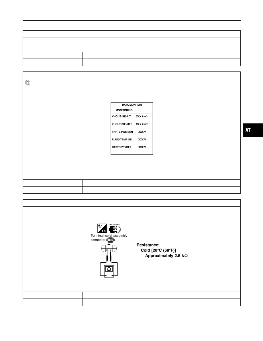
CHECK INPUT SIGNAL OF A/T FLUID TEMPERATURE SENSOR (With CONSULT-II)
With CONSULT-II
1. Start engine.
2. Select “TCM INPUT SIGNALS” in “DATA MONITOR” mode for “A/T” with CONSULT-II.
3. Read out the value of “FLUID TEMP SE”.
SAT614J
Voltage:
Cold [20°C (68°F)]
→
Hot [80°C (176°F)]:
Approximately 1.5V
→
0.5V
OK or NG
OK
©
GO TO 7.
NG
©
GO TO 3.
3
CHECK A/T FLUID TEMPERATURE SENSOR WITH TERMINAL CORD ASSEMBLY
1. Turn ignition switch to OFF position.
2. Disconnect terminal cord assembly connector in engine compartment.
3. Check resistance between terminals 6 (G) and 7 (B) when A/T is cold.
SAT616JA
4. Reinstall any part removed.
OK or NG
OK
©
GO TO 4.
NG
©
GO TO 5.
GI
MA
EM
LC
EC
FE
AX
SU
BR
ST
RS
BT
HA
SC
EL
IDX
DTC P0710 A/T FLUID TEMPERATURE SENSOR CIRCUIT
Diagnostic Procedure
AT-117
4
DETECT MALFUNCTIONING ITEM
Check the following items:
I
Harness for short to ground or short to power or open between TCM, ECM and terminal cord assembly
I
Ground circuit for ECM
Refer to EC-153, “TROUBLE DIAGNOSIS FOR POWER SUPPLY”.
OK or NG
OK
©
GO TO 7.
NG
©
Repair or replace damaged parts.
5
DETECT MALFUNCTIONING ITEM
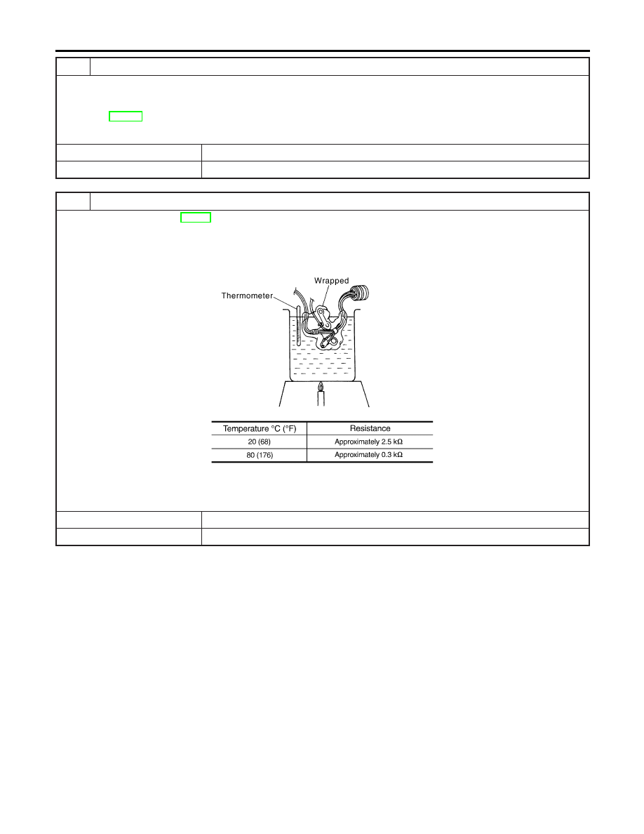
1. Remove oil pan, refer to AT-282.
2. Check the following items:
I
A/T fluid temperature sensor
Check resistance between A/T fluid temperature sensor harness connector F92 terminals 6 (G) and 7 (B) while chang-
ing temperature as shown at below.
SAT821K
MTBL0210
I
Harness of terminal cord assembly for short or open
OK or NG
OK
©
GO TO 7.
NG
©
Repair or replace damaged parts.
DTC P0710 A/T FLUID TEMPERATURE SENSOR CIRCUIT
Diagnostic Procedure (Cont’d)
AT-118
6
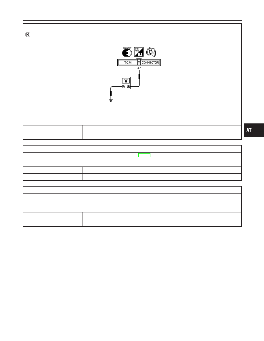
CHECK INPUT SIGNAL OF A/T FLUID TEMPERATURE SENSOR (Without CONSULT-II)
Without CONSULT-II
1. Start engine.
2. Check voltage between TCM harness connector F50 terminal 47 (G) and ground while warming up A/T.
SAT335JA
Voltage:
Cold [20°C (68°F)]
→
Hot [80°C (176°F)]:
Approximately 1.5V
→
0.5V
OK or NG
OK
©
GO TO 7.
NG
©
GO TO 3.
7
CHECK DTC
Perform Diagnostic Trouble Code (DTC) confirmation procedure, AT-115.
OK or NG
OK
©
INSPECTION END
NG
©
GO TO 8.
8
CHECK TCM INSPECTION
1. Perform TCM input/output signal inspection.
2. If NG, recheck TCM pin terminals for damage or loose connection with harness connector.
OK or NG
OK
©
INSPECTION END
NG
©
Repair or replace damaged parts.
GI
MA
EM
LC
EC
FE
AX
SU
BR
ST
RS
BT
HA
SC
EL
IDX
DTC P0710 A/T FLUID TEMPERATURE SENSOR CIRCUIT
Diagnostic Procedure (Cont’d)
AT-119
SAT644J
Description
NHAT0040
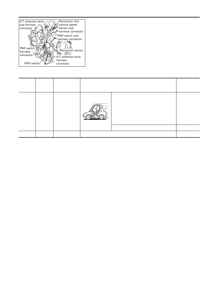
The revolution sensor detects the revolution of the idler gear park-
ing pawl lock gear and emits a pulse signal. The pulse signal is sent
to the TCM which converts it into vehicle speed.
TCM TERMINALS AND REFERENCE VALUE
NHAT0040S01
Remarks: Specification data are reference values.
Terminal
No.
Wire color
Item
Condition
Judgement
standard
(Approx.)
29
W
Revolution
sensor
When moving at 20 km/h (12 MPH), use the
CONSULT-II pulse frequency measuring func-
tion.*1
CAUTION:
Connect the diagnosis data link cable to
the vehicle diagnosis connector.
*1: A circuit tester cannot be used to test this
item.
450 Hz
When vehicle parks.
0V
42
B
Sensor ground
—
0V
On Board Diagnosis Logic
NHAT0207
Diagnostic trouble code VEH SPD SEN/CIR AT with CONSULT-II
or P0720 without CONSULT-II is detected when TCM does not
receive the proper voltage signal from the sensor.
Possible Cause
NHAT0208
Check the following items.
I
Harness or connectors
(The sensor circuit is open or shorted.)
I
Revolution sensor
DTC P0720 VEHICLE SPEED SENSOR·A/T (REVOLUTION SENSOR)
Description
AT-120
Нет комментариевНе стесняйтесь поделиться с нами вашим ценным мнением.
Текст