Infiniti I35 (A33). Manual — part 141
4
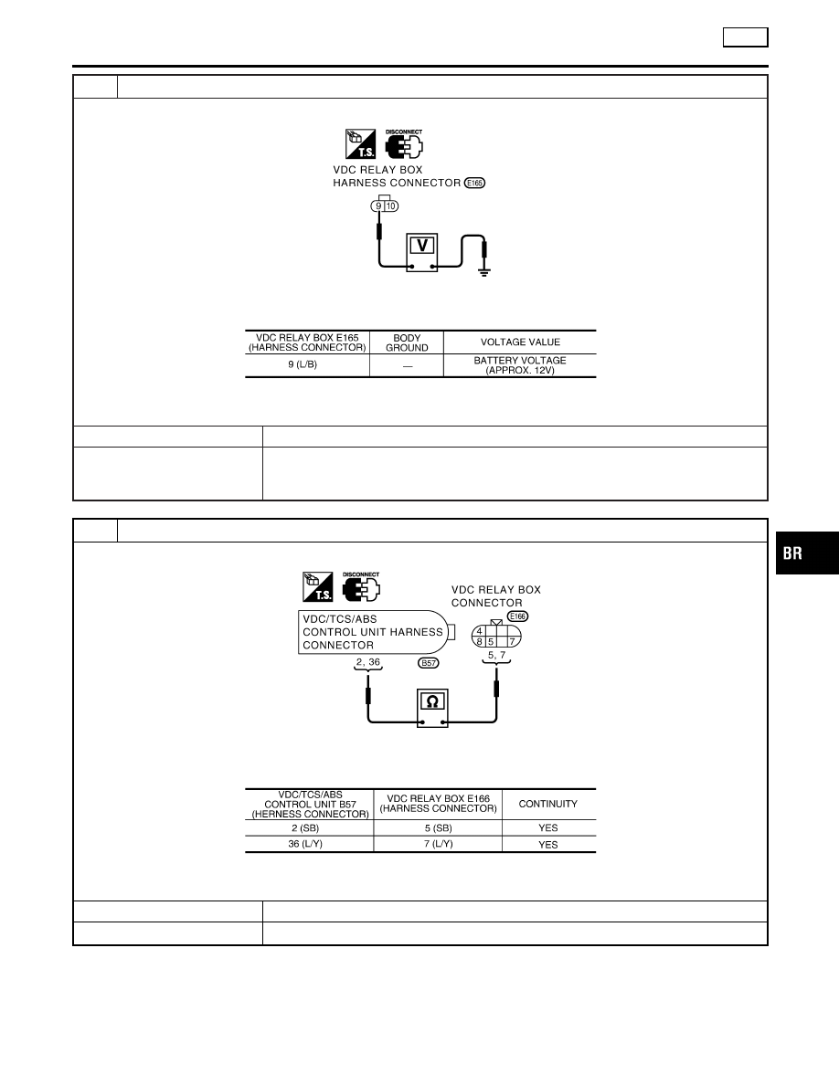
ACTUATOR RELAY POWER SUPPLY CIRCUIT INSPECTION
1. Disconnect VDC relay box connector E165.
SBR206F
2. Check the voltage between the harness connector E165 and body ground.
MTBL1392
Is inspection result OK?
Yes
©
GO TO 5.
No
©
I
Check the fuse 30A.
I
Check for continuity between the battery and the VDC relay box connector E165 ter-
minal No. 9. If it is not OK, replace the fuse or harness.
5
ACTUATOR RELAY POWER CIRCUIT CHECK
1. Disconnect connectors for the VDC/TCS/ABS control unit and the VDC relay box.
SBR208F
2. Check for continuity between the VDC/TCS/ABS control unit and the VDC relay box (harness connectors B57 and
E166).
MTBL1393
Is inspection result OK?
OK
©
GO TO 6.
NG
©
Harness disconnection between the VDC/TCS/ABS control unit and the VDC relay box.
GI
MA
EM
LC
EC
FE
AT
AX
SU
ST
RS
BT
HA
SC
EL
IDX
TROUBLE DIAGNOSES FOR SELF-DIAGNOSTIC ITEMS
VDC
Inspection 9 Actuator Relay and Circuit (Cont’d)
BR-149
6
ACTUATOR RELAY UNIT INSPECTION
Check the actuator relay as a unit.
Is inspection result OK?
OK
©
Check the VDC/TCS/ABS control unit power supply circuit.
NG
©
Replace the actuator relay.
Inspection 10 Stop Lamp Switch and Circuit
NHBR0279
Inspection procedure
1
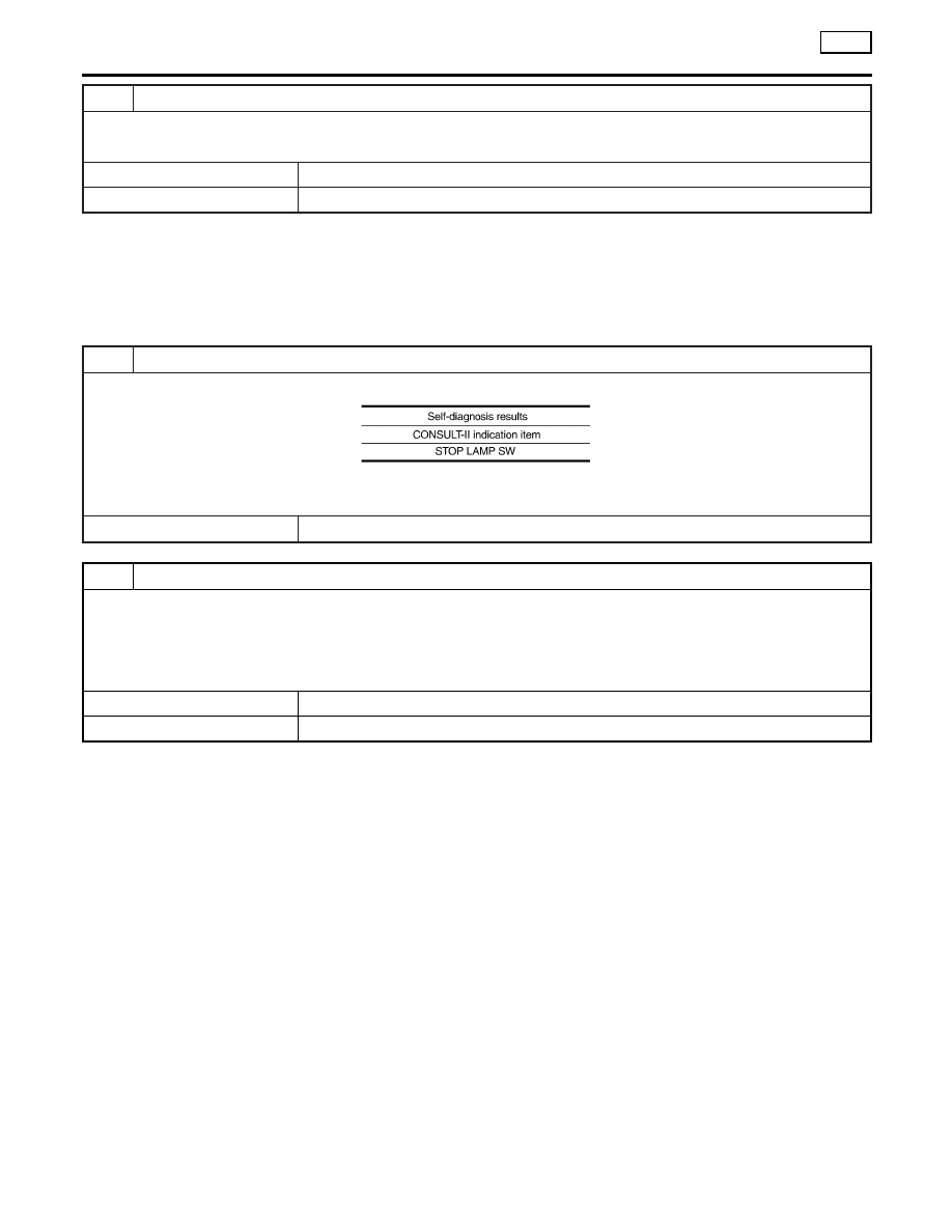
SELF-DIAGNOSIS RESULT CHECK
Check the self-diagnosis results.
MTBL1286
Is “STOP LAMP SW” indicated in the self-diagnosis results?
©
GO TO 2.
2
STOP LAMP INSPECTION
1. Disconnect connectors for the stop lamp switch and the VDC/TCS/ABS control unit.
2. Securely connect them again.
3. Start the engine.
4. Repeat depressing the brake pedal carefully several times, then perform the self-diagnosis again.
Is the same self-diagnosis item indicated?
Yes
©
GO TO 3.
No
©
Repair or replace the poorly connected connector.
TROUBLE DIAGNOSES FOR SELF-DIAGNOSTIC ITEMS
VDC
Inspection 9 Actuator Relay and Circuit (Cont’d)
BR-150
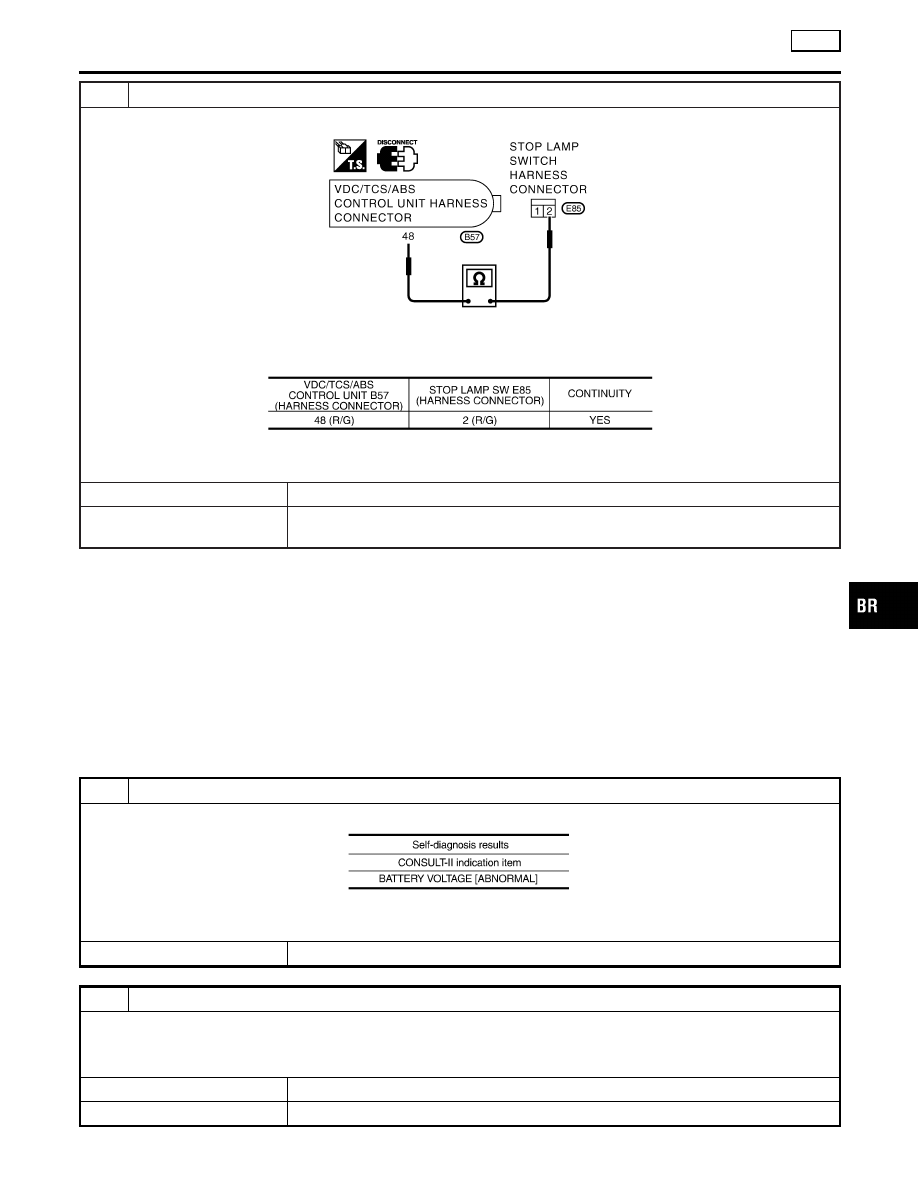
3
STOP LAMP SWITCH CIRCUIT CHECK
1. Disconnect connectors for the stop lamp switch and the VDC/TCS/ABS control unit.
SBR210F
2. Check for continuity between the stop lamp switch (harness connector E85) and the VDC/TCS/ABS control unit (har-
ness connector B57).
MTBL1394
Is inspection result OK?
OK
©
Perform the VDC/TCS/ABS control unit self-diagnosis again.
NG
©
Harness disconnection between the VDC/TCS/ABS control unit and the stop lamp
switch.
Inspection 11 VDC/TCS/ABS Control Unit
Power Supply Circuit
NHBR0280
Inspection procedure
1
SELF-DIAGNOSIS RESULT CHECK 1
Check the self-diagnosis results.
MTBL1288
Is “BATTERY VOLTAGE [ABNORMAL]” indicated in the self-diagnosis results?
©
GO TO 2.
2
SELF-DIAGNOSIS RESULT CHECK 2
1. Disconnect the VDC/TCS/ABS control unit connector B57. Securely connect them again.
2. Perform the self-diagnosis.
Is the same self-diagnosis item indicated?
Yes
©
GO TO 3.
No
©
Repair or replace the poorly connected connector.
GI
MA
EM
LC
EC
FE
AT
AX
SU
ST
RS
BT
HA
SC
EL
IDX
TROUBLE DIAGNOSES FOR SELF-DIAGNOSTIC ITEMS
VDC
Inspection 10 Stop Lamp Switch and Circuit (Cont’d)
BR-151
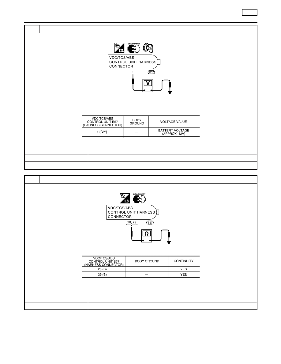
3
VDC/TCS/ABS CONTROL UNIT POWER SUPPLY CIRCUIT INSPECTION 1
1. Disconnect the VDC/TCS/ABS control unit connector B57.
SBR212F
2. Turn the ignition switch ON (engine not running), and check the voltage between the VDC/TCS/ABS control unit (har-
ness connector B57) and body ground.
MTBL1395
Is inspection result OK?
Yes
©
GO TO 4.
No
©
GO TO 5.
4
VDC/TCS/ABS CONTROL UNIT GROUND CIRCUIT INSPECTION 1
Check the VDC/TCS/ABS control unit ground circuit (harness connector B57).
SBR214F
MTBL1396
Is inspection result OK?
OK
©
Perform the VDC/TCS/ABS control unit self-diagnosis again.
NG
©
Harness disconnection or improper installation of the VDC/TCS/ABS control unit.
TROUBLE DIAGNOSES FOR SELF-DIAGNOSTIC ITEMS
VDC
Inspection 11 VDC/TCS/ABS Control Unit Power Supply Circuit (Cont’d)
BR-152
Нет комментариевНе стесняйтесь поделиться с нами вашим ценным мнением.
Текст