Infiniti I35 (A33). Manual — part 552
I
Cooling unit (Evaporator)
With engine OFF, turn blower fan on “High” for at least 15
seconds to dissipate any refrigerant trace in the cooling unit.
Wait a minimum of 10 minutes accumulation time (refer to the
manufacturer’s recommended procedure for actual wait time)
before inserting the leak detector probe into the drain hose.
Keep the probe inserted for at least ten seconds. Use caution
not to contaminate the ptobe tip with water or dirt that may be
in the drain hose.
5.
If a leak detector detects a leak, verify at least once by blow-
ing compressed air into area of suspected leak, then repeat
check as outlined above.
6.
Do not stop when one leak is found. Continue to check for
additional leaks at all system components.
If no leaks are found, perform steps 7 - 10.
7.
Start engine.
8.
Set the heater A/C control as follows:
1)
A/C switch ON.
2)
Face mode
3)
Recirculation switch ON
4)
Max cold temperature
5)
Fan speed high
9.
Run engine at 1,500 rpm for at least 2 minutes.
10. Turn engine off and perform leak check again following steps
4 through 6 above.
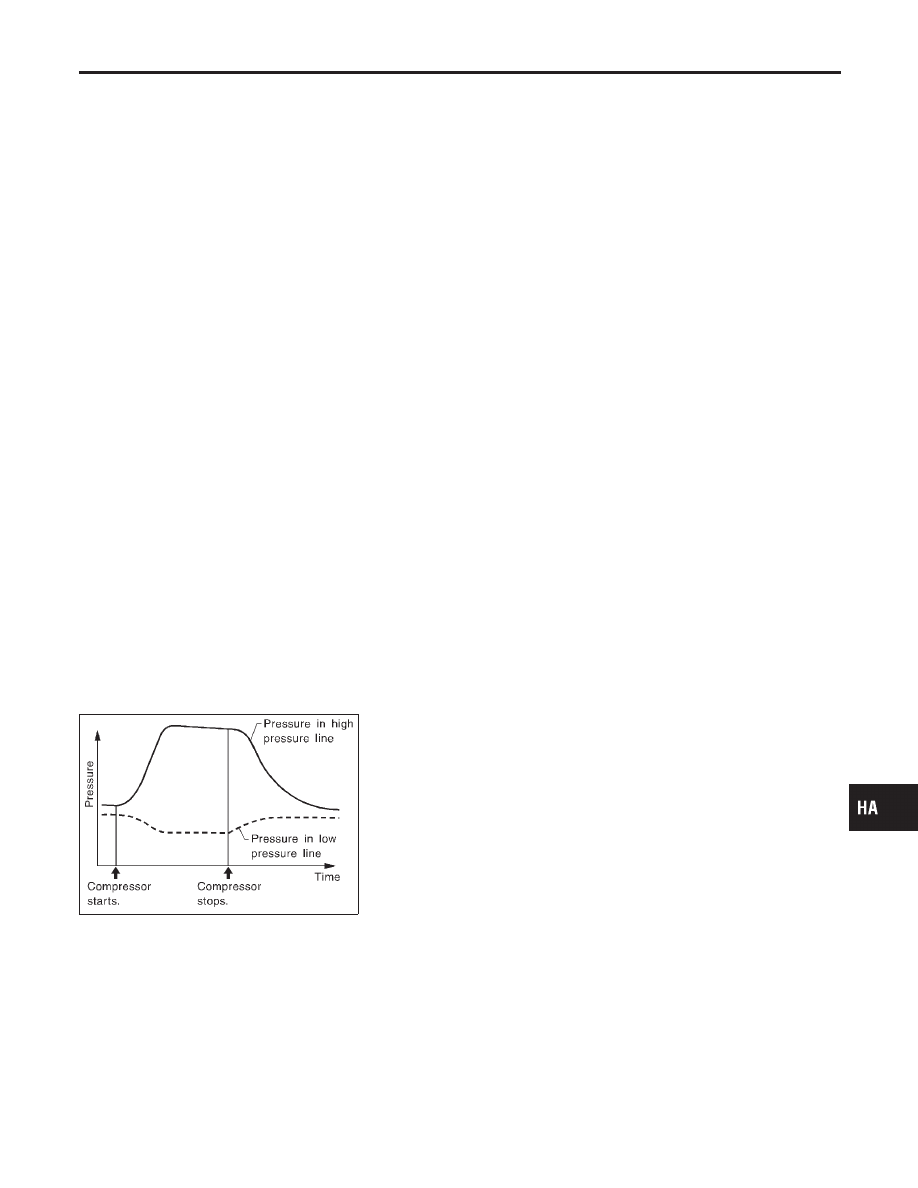
SHA839E
Refrigerant leaks should be checked immediately after
stopping the engine. Begin with the leak detector at the
compressor. The pressure on the high pressure side will
gradually drop after refrigerant circulation stops and pres-
sure on the low pressure side will gradually rise, as shown
in the graph. Some leaks are more easily detected when
pressure is high.
11. Before connecting Recovery/Recycling Recharging equipment
to vehicle, check Recovery/Recycling Recharging equipment
gauges. No refrigerant pressure should be displayed. If pres-
sure is displayed, recover refrigerant from equipment lines and
then check refrigerant purity.
12. Confirm refrigerant purity in supply tank using Recovery/
Recycling Recharging equipment and refrigerant identifier.
13. Confirm refrigerant purity in vehicle A/C system using
Recovery/Recycling Recharging equipment and refrigerant
identifier.
14. Discharge A/C system using approved refrigerant recovery
GI
MA
EM
LC
EC
FE
AT
AX
SU
BR
ST
RS
BT
SC
EL
IDX
SERVICE PROCEDURE
Refrigerant Lines (Cont’d)
HA-121
equipment. Repair the leaking fitting or component as neces-
sary.
15. Evacuate and recharge A/C system and perform the leak test
to confirm no refrigerant leaks.
16. Conduct A/C performance test to ensure system works
properly.
Fluorescent Dye Leak Detector
PRECAUTIONS FOR FLUORESCENT DYE LEAK
DETECTION
NHHA0274
I
The fluorescent dye leak detector is not a replacement for an
electronic refrigerant leak detector. The fluorescent dye leak
detector should be used in conjunction with an electronic
refrigerant leak detector (J-41995) to pinpoint refrigerant leaks.
I
For your safety and your customer’s satisfaction, read and fol-
low all manufacturer’s operating instructions and precautions
prior to performing the work.
I
Refer to “Precautions for Leak Detection Dye”, HA-3.
CHECKING SYSTEM FOR LEAKS USING THE
FLUORESCENT LEAK DETECTOR
NHHA0275
1.
Check A/C system for leaks using the UV lamp and UV safety
goggles (J-42220) in a low sunlight area (area without windows
preferable). Illuminate all components, fittings and lines. The
dye will appear as a bright green/yellow area at the point of
leakage. Fluorescent dye observed at the evaporator drain
opening indicates an evaporator core assembly (tubes, core or
thermal expansion valve) leak.
2.
If the suspected area is difficult to see, use an adjustable mir-
ror or wipe the area with a clean shop rag or cloth, then check
the cloth with the UV lamp for dye residue.
3.
Confirm any suspected leaks with an approved electronic
refrigerant leak detector.
4.
After the leak is repaired, remove any residual dye using dye
cleaner (J-43872) or prevent future misdiagnosis.
5.
Perform a system performance check and verify the leak repair
with an approved electronic refrigerant leak detector.
DYE INJECTION
NHHA0276
(This procedure is only necessary when re-charging the system or
when the compressor has seized and was replaced.)
Refer to “Precaution for Leak Detection Dye”, HA-3.
1.
Check A/C system static (at rest) pressure. Pressure must be
at least 345 kPa (3.5 kg/cm
2
, 50 psi).
2.
Pour one bottle (1/4 ounce/7.4 cc) of the A/C refrigerant dye
into the injector tool (J-41459).
3.
Connect the injector tool to the A/C LOW PRESSURE side
sevice fitting.
4.
Start engine and switch A/C ON.
5.
With the A/C operating (compressor running), inject one bottle
(1/4 ounce/7.4 cc) of fluorescent dye through the low-pressure
service valve using dye injector tool J-41459 (refer to the
manufacture’s operating instructions).
SERVICE PROCEDURE
Refrigerant Lines (Cont’d)
HA-122
6.
With the engine still running, disconnect the injector tool from
the service fitting.
CAUTION:
Be careful not to allow dye to spray or drip when disconnect-
ing the injector from the system.
NOTE:
If repairing the A/C system or replacing a component, pour the dye
directly into the open system connection and proceed with the ser-
vice procedures.
7.
Operate the A/C system for a minimum of 20 minutes to mix
the dye with the system oil. Depending on the leak size, oper-
ating conditions and location of the leak, it may take from min-
utes to days for the dye to penetrate a leak and become visible.
Belt
TENSION ADJUSTMENT
NHHA0237
I
Refer to MA-13, “Checking Drive Belt”.
SHA643F
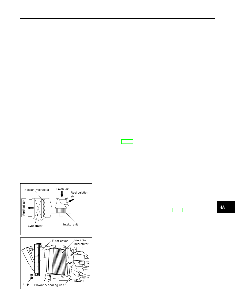
In-cabin Microfilter
FUNCTION
NHHA0271
Air inside passenger compartment is kept clean at either recircula-
tion or fresh mode by installing in-cabin microfilter into cooling unit.
NOTE:
To replace in-cabin microfilter, refer to MA-6, “Periodic Main-
tenance”.
Caution label is fixed inside the glove box.
SHA644F
REPLACEMENT PROCEDURE
NHHA0272
1.
Remove glove box.
2.
Remove instrument lower panel from instrument panel.
3.
Remove filter cover fixed clip.
4.
Slide the filter cover to the upper side and then remove it.
5.
Take out the in-cabin microfilter from cooling unit.
6.
Replace with new one and reinstall on cooling unit.
7.
Reinstall filter cover, clip, instrument lower panel and glove
box.
GI
MA
EM
LC
EC
FE
AT
AX
SU
BR
ST
RS
BT
SC
EL
IDX
SERVICE PROCEDURE
Fluorescent Dye Leak Detector (Cont’d)
HA-123
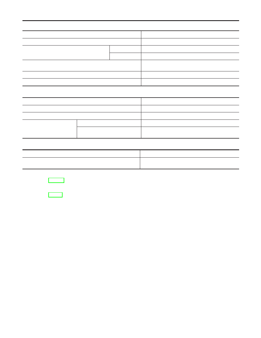
Compressor
NHHA0241
Model
Calsonic Kansei make V-6
Type
V-6 variable displacement
Displacement
cm
3
(cu in)/rev.
Max.
184 (11.228)
Min.
14.5 (0.885)
Cylinder bore x stroke
mm (in)
37 (1.46) x [2.3 - 28.6 (0.091 - 1.126)]
Direction of rotation
Clockwise (viewed from drive end)
Drive belt
Poly V
Lubricant
NHHA0242
Model
Calsonic Kansei make V-6
Name
Nissan A/C System Oil Type S
Part number
KLH00-PAGS0
Capacity
m
(US fl oz, Imp fl oz)
Total in system
180 (6.1, 6.3)
Compressor (Service part) charging
amount
180 (6.1, 6.3)
Refrigerant
NHHA0243
Type
HFC-134a (R-134a)
Capacity
kg (lb)
0.50 (1.10)
Engine Idling Speed (When A/C is ON)
NHHA0244
I
Refer to EC-739, “Idle Speed and Ignition Timing”.
Belt Tension
NHHA0245
I
Refer to MA-13, “Checking Drive Belts”.
SERVICE DATA AND SPECIFICATIONS (SDS)
Compressor
HA-124
Нет комментариевНе стесняйтесь поделиться с нами вашим ценным мнением.
Текст