Infiniti I35 (A33). Manual — part 185
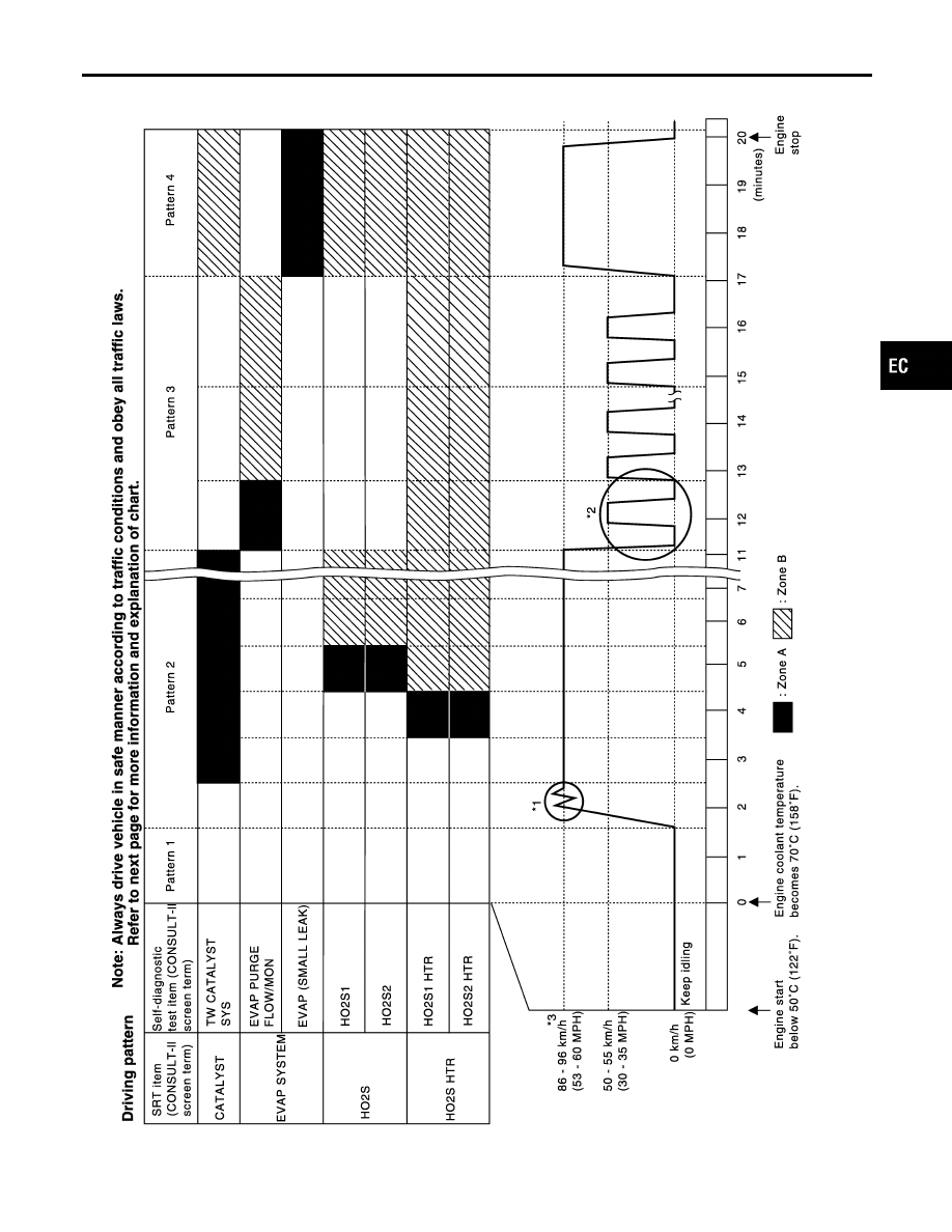
Driving Pattern
NHEC0031S0303
SEC390D
GI
MA
EM
LC
FE
AT
AX
SU
BR
ST
RS
BT
HA
SC
EL
IDX
ON BOARD DIAGNOSTIC SYSTEM DESCRIPTION
Emission-related Diagnostic Information (Cont’d)
EC-81
I
The time required for each diagnosis varies with road surface conditions, weather, altitude, individual driv-
ing habits, etc.
Zone A refers to the range where the time required, for the diagnosis under normal conditions*, is the
shortest.
Zone B refers to the range where the diagnosis can still be performed if the diagnosis is not completed
within zone A.
*: Normal conditions refer to the following:
−
Sea level
−
Flat road
−
Ambient air temperature: 20 - 30°C (68 - 86°F)
−
Diagnosis is performed as quickly as possible under normal conditions.
Under different conditions [For example: ambient air temperature other than 20 - 30°C (68 - 86°F)], diag-
nosis may also be performed.
Pattern 1:
I
The engine is started at the engine coolant temperature of −10 to 35°C (14 to 95°F)
(where the voltage between the ECM terminal 93 and ground is 3.0 - 4.3V).
I
The engine must be operated at idle speed until the engine coolant temperature is greater than 70°C
(158°F) (where the voltage between the ECM terminal 93 and ground is lower than 1.4V).
I
The engine is started at the fuel tank temperature of warmer than 0°C (32°F) (where the voltage
between the ECM terminal 75 and ground is less than 4.1V).
Pattern 2:
I
When steady-state driving is performed again even after it is interrupted, each diagnosis can be conducted.
In this case, the time required for diagnosis may be extended.
Pattern 3:
I
The driving pattern outlined in *2 must be repeated at least 3 times.
Pattern 4:
I
Tests are performed after the engine has been operated for at least 17 minutes.
I
The accelerator pedal must be held very steady during steady-state driving.
I
If the accelerator pedal is moved, the test must be conducted all over again.
*1: Depress the accelerator pedal until vehicle speed is 90 km/h (56 MPH), then release the accelerator pedal
and keep it released for more than 10 seconds. Depress the accelerator pedal until vehicle speed is 90 km/h
(56 MPH) again.
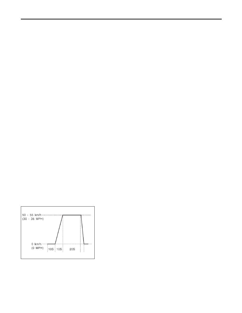
*2: Operate the vehicle in the following driving pattern.
1) Decelerate vehicle to 0 km/h (0 MPH) and let engine idle.
2) Repeat driving pattern shown below at least 10 times.
I
During acceleration, hold the accelerator pedal as steady as possible.
SEF414S
*3: Checking the vehicle speed with GST is advised.
Suggested Transmission Gear Position
Set the selector lever in the “D” position with the overdrive switch turned ON.
ON BOARD DIAGNOSTIC SYSTEM DESCRIPTION
Emission-related Diagnostic Information (Cont’d)
EC-82
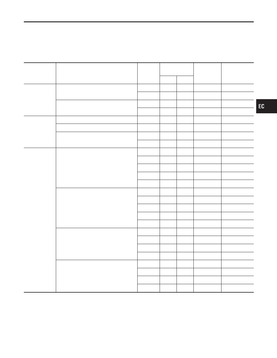
TEST VALUE AND TEST LIMIT (GST ONLY — NOT APPLICABLE TO CONSULT-II)
NHEC0031S04
The following is the information specified in Mode 6 of SAE J1979.
The test value is a parameter used to determine whether a system/circuit diagnostic test is “OK” or “NG” while
being monitored by the ECM during self-diagnosis. The test limit is a reference value which is specified as the
maximum or minimum value and is compared with the test value being monitored.
These data (test value and test limit) are specified by Test ID (TID) and Component ID (CID) and can be dis-
played on the GST screen.
SRT item
Self-diagnostic test item
DTC
Test value (GST
display)
Test limit
Conversion
TID
CID
CATALYST
Three way catalyst function (Bank 1)
P0420
01H
01H
Max.
1/128
P0420
02H
81H
Min.
1
Three way catalyst function (Bank 2)
P0430
03H
02H
Max.
1/128
P0430
04H
82H
Min.
1
EVAP SYSTEM
EVAP control system (Small leak)
P0442
05H
03H
Max.
1/128 mm
2
EVAP control system purge flow monitoring
P0441
06H
83H
Min.
20 mV
EVAP control system (Very small leak)
P0456
07H
03H
Max.
1/128 mm
2
P1456
07H
03H
Max.
1/128 mm
2
HO2S
Heated oxygen sensor 1 (Bank 1)
P0133
09H
04H
Max.
16 ms
P1143
0AH
84H
Min.
10 mV
P1144
0BH
04H
Max.
10 mV
P0132
0CH
04H
Max.
10 mV
P0134
0DH
04H
Max.
1 s
Heated oxygen sensor 1 (Bank 2)
P0153
11H
05H
Max.
16 ms
P1163
12H
85H
Min.
10 mV
P1164
13H
05H
Max.
10 mV
P0152
14H
05H
Max.
10 mV
P0154
15H
05H
Max.
1 s
Heated oxygen sensor 2 (Bank 1)
P0139
19H
86H
Min.
10 mV/500 ms
P1147
1AH
86H
Min.
10 mV
P1146
1BH
06H
Max.
10 mV
P0138
1CH
06H
Max.
10 mV
Heated oxygen sensor 2 (Bank 2)
P0159
21H
87H
Min.
10 mV/500 ms
P1167
22H
87H
Min.
10 mV
P1166
23H
07H
Max.
10 mV
P0158
24H
07H
Max.
10 mV
GI
MA
EM
LC
FE
AT
AX
SU
BR
ST
RS
BT
HA
SC
EL
IDX
ON BOARD DIAGNOSTIC SYSTEM DESCRIPTION
Emission-related Diagnostic Information (Cont’d)
EC-83
SRT item
Self-diagnostic test item
DTC
Test value (GST
display)
Test limit
Conversion
TID
CID
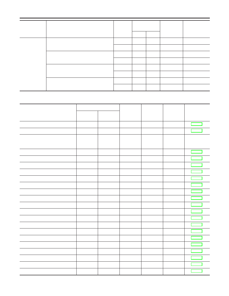
HO2S HTR
Heated oxygen sensor 1 heater (Bank 1)
P0032
29H
08H
Max.
20 mV
P0031
2AH
88H
Min.
20 mV
Heated oxygen sensor 1 heater (Bank 2)
P0052
2BH
09H
Max.
20 mV
P0051
2CH
89H
Min.
20 mV
Heated oxygen sensor 2 heater (Bank 1)
P0038
2DH
0AH
Max.
20 mV
P0037
2EH
8AH
Min.
20 mV
Heated oxygen sensor 2 heater (Bank 2)
P0058
2FH
0BH
Max.
20 mV
P0057
30H
8BH
Min.
20 mV
EMISSION-RELATED DIAGNOSTIC INFORMATION ITEMS
NHEC0031S05
X: Applicable
—: Not applicable
Items
(CONSULT-II screen terms)
DTC*1
SRT code
Test value/
Test limit
(GST only)
1st trip
DTC*1
Reference
page
CONSULT-II
GST*2
ECM*3
CAN COMM CIRCUIT
U1000
1000*5
—
—
—
CAN COMM CIRCUIT
U1001
1001*5
—
—
X
NO DTC IS DETECTED.
FURTHER TESTING
MAY BE REQUIRED.
P0000
0000
—
—
—
—
INT/V TIM CONT-B1
P0011
0011
—
—
X
INT/V TIM CONT-B2
P0021
0021
—
—
X
HO2S1 HTR (B1)
P0031
0031
X
X
X
HO2S1 HTR (B1)
P0032
0032
X
X
X
HO2S2 HTR (B1)
P0037
0037
X
X
X
HO2S2 HTR (B1)
P0038
0038
X
X
X
HO2S1 HTR (B2)
P0051
0051
X
X
X
HO2S1 HTR (B2)
P0052
0052
X
X
X
HO2S2 HTR (B2)
P0057
0057
X
X
X
HO2S2 HTR (B2)
P0058
0058
X
X
X
MAF SEN/CIRCUIT
P0101
0101
—
—
—
MAF SEN/CIRCUIT
P0102
0102
—
—
—
MAF SEN/CIRCUIT
P0103
0103
—
—
—
ABSL PRES SEN/CIRC
P0107
0107
—
—
X
ABSL PRES SEN/CIRC
P0108
0108
—
—
X
IAT SEN/CIRCUIT
P0112
0112
—
—
X
IAT SEN/CIRCUIT
P0113
0113
—
—
X
ECT SEN/CIRC
P0117
0117
—
—
—
ECT SEN/CIRC
P0118
0118
—
—
—
ON BOARD DIAGNOSTIC SYSTEM DESCRIPTION
Emission-related Diagnostic Information (Cont’d)
EC-84
Нет комментариевНе стесняйтесь поделиться с нами вашим ценным мнением.
Текст