Infiniti I35 (A33). Manual — part 572
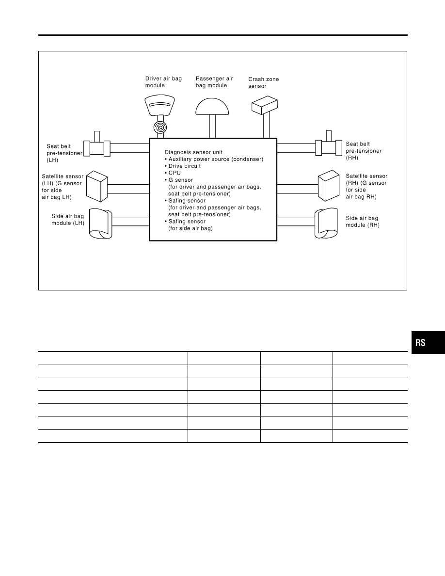
SRS Configuration
=NHRS0010
SRS901
The air bag deploys if the diagnosis sensor unit activates while the ignition switch is in the “ON” or “START”
position.
The collision modes for which supplemental restraint systems are activated are different among the SRS sys-
tems. For example, the driver air bag module and passenger air bag module are activated in a frontal colli-
sion but not in a side collision.
SRS configurations which are activated for some collision modes are as follows;
SRS configuration
Frontal collision
Left side collision
Right side collision
Driver air bag module
X
—
—
Passenger air bag module
X
—
—
Seat belt pre-tensioner (LH)
X
—
—
Seat belt pre-tensioner (RH)
X
—
—
Side air bag module (LH)
—
X
—
Side air bag module (RH)
—
—
X
GI
MA
EM
LC
EC
FE
AT
AX
SU
BR
ST
BT
HA
SC
EL
IDX
SUPPLEMENTAL RESTRAINT SYSTEM (SRS)
SRS Configuration
RS-15
SRS444
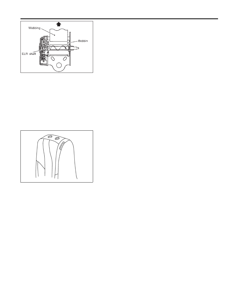
Seat Belt Pre-tensioner with Load Limiter
=NHRS0034
The seat belt pre-tensioner system with load limiter is installed to
both the driver’s seat and the front passenger’s seat. It operates
simultaneously with the SRS air bag system in the event of a fron-
tal collision with an impact exceeding a specified level.
When the frontal collision with an impact exceeding a specified
level occurs, seat belt slack resulting from clothing or other factors
is immediately taken up by the pre-tensioner. Vehicle passengers
are securely restrained.
When passengers in a vehicle are thrown forward in a collision and
the restraining force of the seat belt exceeds a specified level, the
load limiter permits the specified extension of the seat belt by the
twisting of the ELR shaft, and a relaxation of the chest-area seat
belt web tension while maintaining force.
SRS988
Side Air Bag
NHRS0035
Front side air bag is built-in type.
The front seat backs with built-in type side air bag have the labels
shown in figure at left.
SUPPLEMENTAL RESTRAINT SYSTEM (SRS)
Seat Belt Pre-tensioner with Load Limiter
RS-16
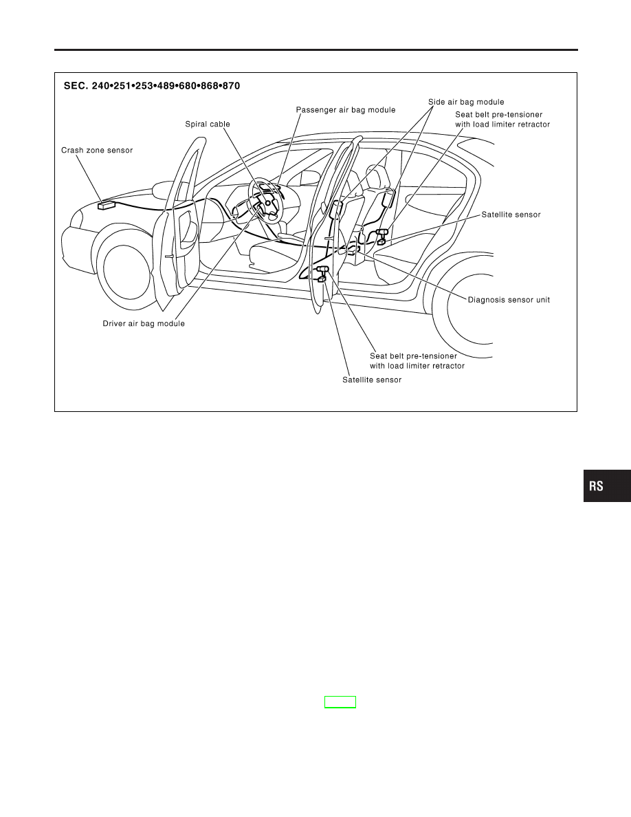
SRS Component Parts Location
NHRS0011
SRS902
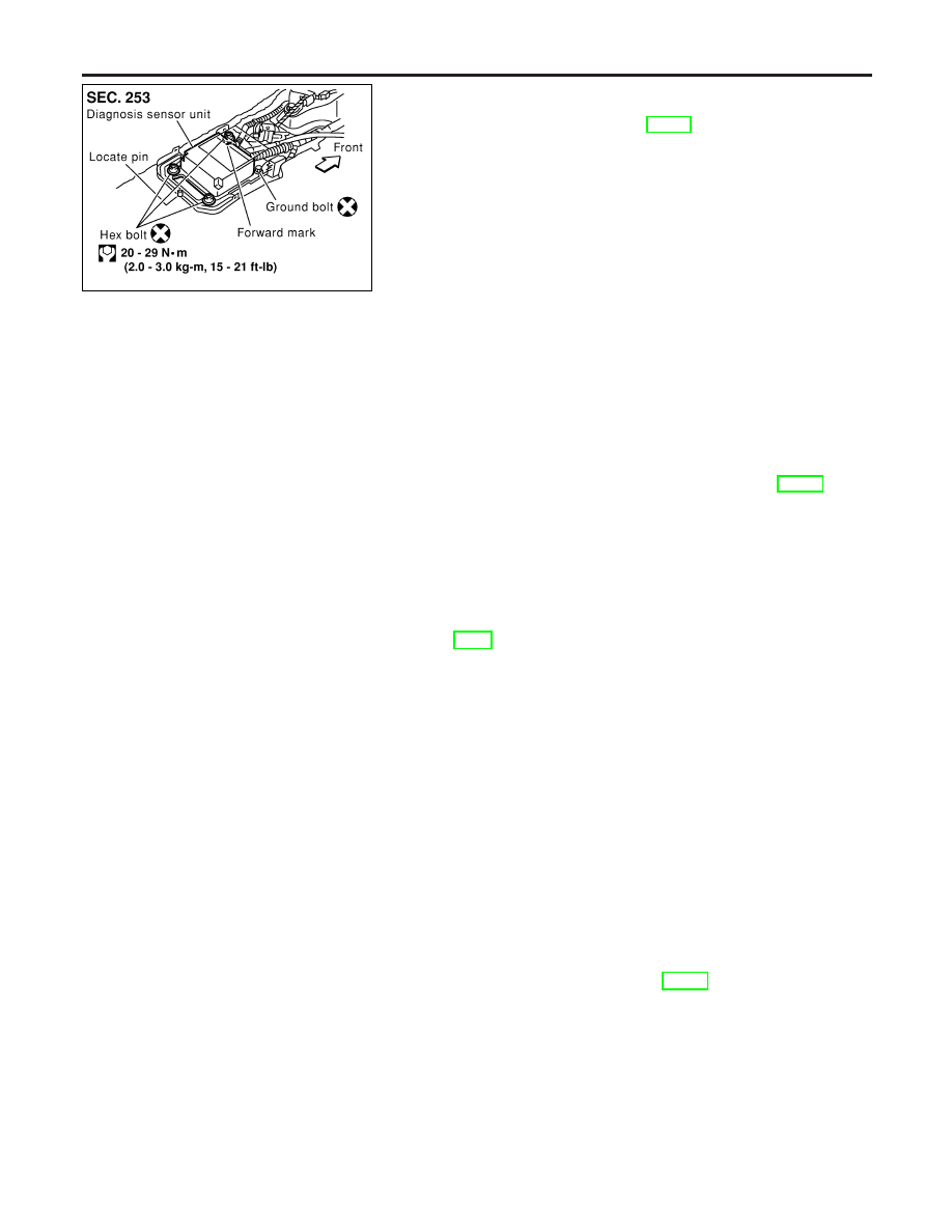
Diagnosis Sensor Unit
REMOVAL AND INSTALLATION
NHRS0013
CAUTION:
I
Before servicing SRS, turn the ignition switch off, discon-
nect both battery cables and wait at least 3 minutes.
I
Do not use old bolts after removal; replace with new ones.
I
Check diagnosis sensor unit for proper installation.
I
Check diagnosis sensor unit to ensure it is free of
deformities, dents, cracks or rust. If they show any visible
signs of damage, replace them with new ones.
I
Check diagnosis sensor unit brackets to ensure they are
free of deformities or rust.
I
Replace diagnosis sensor unit if it has been dropped or
sustained an impact.
I
After replacement of diagnosis sensor unit, perform self-
diagnosis for SRS. Refer to “SRS Operation Check” for
details. (RS-41)
GI
MA
EM
LC
EC
FE
AT
AX
SU
BR
ST
BT
HA
SC
EL
IDX
SUPPLEMENTAL RESTRAINT SYSTEM (SRS)
SRS Component Parts Location
RS-17
SRS978
1.
Disconnect driver, passenger and side air bag module connec-
tors. Also, disconnect seat belt pre-tensioner connector.
2.
Remove console box. Refer to BT-30, “ INSTRUMENT PANEL
ASSEMBLY”.
3.
Disconnect diagnosis sensor unit connector.
4.
Remove ground bolt and also remove bolts from diagnosis
sensor unit.
Then remove the diagnosis sensor unit.
NOTE:
I
To install, reverse the removal procedure sequence.
Seat Belt Pre-tensioner
REMOVAL AND INSTALLATION
NHRS0036
CAUTION:
I
Before servicing SRS, turn the ignition switch off, discon-
nect both battery cables and wait at least 3 minutes.
I
Check seat belt pre-tensioner with load limiter for proper
installation.
I
After replacement of seat belt pre-tensioner, check SRS
function and perform self-diagnosis for SRS.
Refer to “SRS Operation Check” for details. (RS-41)
I
Do not attempt to disassemble seat belt pre-tensioner with
load limiter.
I
Replace seat belt pre-tensioner if it has been dropped or
sustained an impact.
I
Do not expose seat belt pre-tensioner to temperatures
exceeding 80°C (176°F).
For removal of seat belt pre-tensioner, refer to “Front Seat Belt” for
details. (RS-4)
NOTE:
I
To install, reverse the removal procedure sequence.
Crash Zone Sensor
REMOVAL AND INSTALLATION
NHRS0054
CAUTION:
I
Before servicing SRS, turn the ignition switch off, discon-
nect both battery cables and wait at least 3 minutes.
I
Do not use old nuts after removal; replace with new ones.
I
Check crash zone sensor for proper installation.
I
Check crash zone sensor to ensure they are free of
deformities, dents, cracks or rust. If it shows any visible
signs of damage, replace it with new one.
I
After replacement of crash zone sensor, check SRS func-
tion and perform self-diagnosis for SRS. Refer to “SRS
Operation Check” for details. (RS-41)
I
Do not attempt to disassemble crash zone sensor.
I
Replace crash zone sensor if it has been dropped or sus-
tained an impact.
SUPPLEMENTAL RESTRAINT SYSTEM (SRS)
Diagnosis Sensor Unit (Cont’d)
RS-18
Нет комментариевНе стесняйтесь поделиться с нами вашим ценным мнением.
Текст