Infiniti I35 (A33). Manual — part 36
3
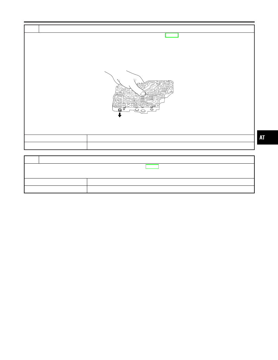
CHECK CONTROL VALVE
1. Disassemble control valve assembly. Refer to “Control Valve Assembly”, AT-314.
2. Check to ensure that:
I
Valve, sleeve and plug slide along valve bore under their own weight.
I
Valve, sleeve and plug are free from burrs, dents and scratches.
I
Control valve springs are free from damage, deformation and fatigue.
I
Hydraulic line is free from obstacles.
SAT367H
OK or NG
OK
©
GO TO 4.
NG
©
Repair control valve assembly.
4
CHECK DTC
Perform Diagnostic Trouble Code (DTC) confirmation procedure, AT-137.
OK or NG
OK
©
INSPECTION END
NG
©
Check transaxle iner parts. (Clutch, brake, etc.)
GI
MA
EM
LC
EC
FE
AX
SU
BR
ST
RS
BT
HA
SC
EL
IDX
DTC P0732 A/T 2ND GEAR FUNCTION
Diagnostic Procedure (Cont’d)
AT-141
Description
NHAT0052
I
This malfunction will not be detected while the A/T CHECK
indicator lamp is indicating another self-diagnosis malfunction.
I
This malfunction is detected when the A/T does not shift into
third gear position as instructed by the TCM. This is not caused
by electrical malfunction (circuits open or shorted) but by
mechanical malfunction such as control valve sticking,
improper solenoid valve operation, malfunctioning servo piston
or brake band, etc.
Gear position
1
2
3
4
Shift solenoid valve A
ON (Closed)
OFF (Open)
OFF (Open)
ON (Closed)
Shift solenoid valve B
ON (Closed)
ON (Closed)
OFF (Open)
OFF (Open)
TCM TERMINALS AND REFERENCE VALUE
NHAT0052S01
Remarks: Specification data are reference values.
Terminal
No.
Wire color
Item
Condition
Judgement
standard
(Approx.)
11
R/Y
Shift solenoid valve
A
When shift solenoid valve A operates.
(When driving in D
1
or D
4
.)
Battery volt-
age
When shift solenoid valve A does not operate.
(When driving in D
2
or D
3
.)
0V
On Board Diagnosis Logic
NHAT0219
This diagnosis monitors actual gear position by checking the torque
converter slip ratio calculated by TCM as follows:
Torque converter slip ratio = A x C/B
A: Output shaft revolution signal from revolution sensor
B: Engine speed signal from ECM
C: Gear ratio determined as gear position which TCM supposes
If the actual gear position is higher than the position (3rd) supposed
by TCM, the slip ratio will be more than normal. In case the ratio
exceeds the specified value, TCM judges this diagnosis malfunc-
tion.
This malfunction will be caused when shift solenoid valve A is stuck
closed.
Gear positions supposed by TCM are as follows.
In case of gear position with no malfunctions: 1, 2, 3 and 4 posi-
tions
In case of gear position with shift solenoid valve A stuck closed: 1,
1, 4* and 4 positions to each gear position above
*: P0733 is detected.
Diagnostic trouble code A/T 3RD GR FNCTN with CONSULT-II or
P0733 without CONSULT-II is detected when A/T cannot be shifted
to the 3rd gear position even if electrical circuit is good.
DTC P0733 A/T 3RD GEAR FUNCTION
Description
AT-142
Possible Cause
NHAT0220
Check the following items.
I
Shift solenoid valve A
I
Each clutch
I
Hydraulic control circuit
SAT014K
SAT860K
SAT021J
Diagnostic Trouble Code (DTC) Confirmation
Procedure
NHAT0221
CAUTION:
I
Always drive vehicle at a safe speed.
I
Be careful not to rev engine into the red zone on the
tachometer.
NOTE:
If “DTC Confirmation Procedure” has been previously conducted,
always turn ignition switch “OFF” and wait at least 10 seconds
before conducting the next test.
TESTING CONDITION:
Always drive vehicle on a level road to improve the accuracy
of test.
After the repair, perform the following procedure to confirm the
malfunction is eliminated.
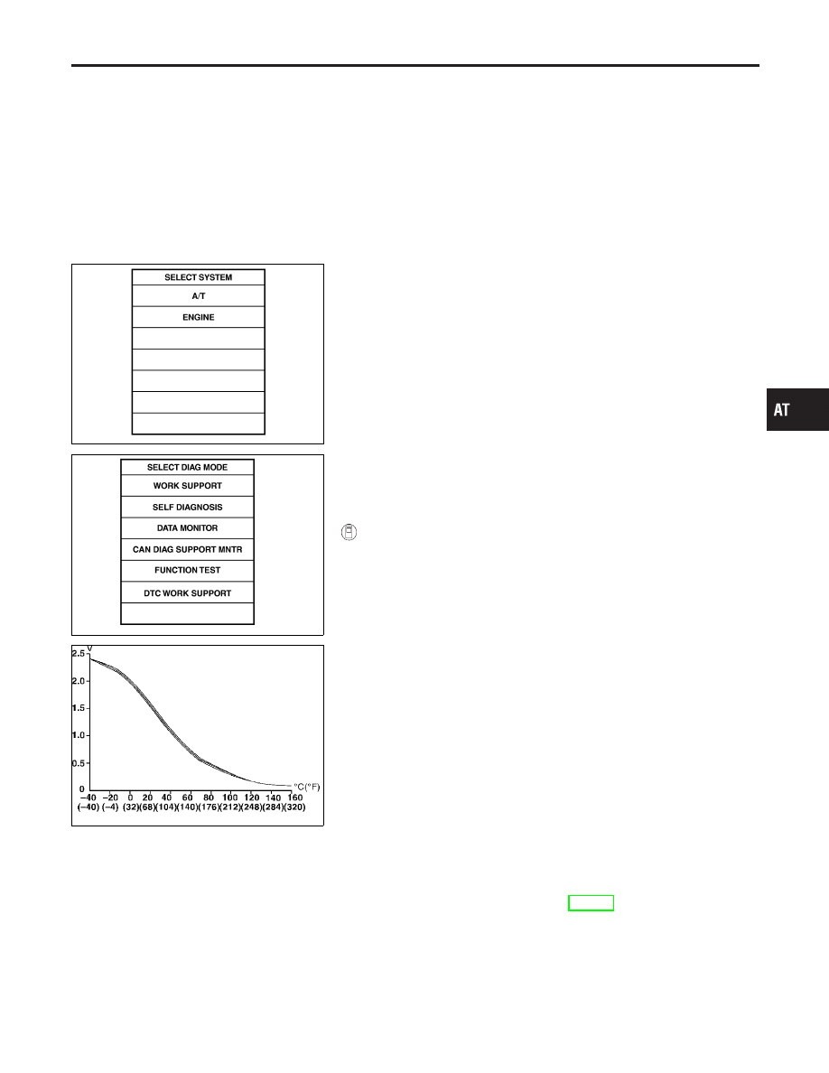
WITH CONSULT-II
NHAT0221S01
1)
Start engine and select “DATA MONITOR” mode for “A/T” with
CONSULT-II.
2)
Make sure that output voltage of A/T fluid temperature sensor
is within the range below.
FLUID TEMP SEN: 0.4 - 1.5V
If out of range, drive the vehicle to decrease the voltage (warm
up the fluid) or stop engine to increase the voltage (cool down
the fluid).
3)
Select “3RD GR FNCTN P0733” of “DTC WORK SUPPORT”
mode for “A/T” with CONSULT-II and touch “START”.
4)
Accelerate vehicle to 60 to 75 km/h (37 to 47 MPH) under the
following condition and release the accelerator pedal com-
pletely.
THROTTLE POSI: Less than 1.0/8 (at all times during step
4)
Selector lever: D position
I
Check that “GEAR” shows “4” after releasing pedal.
5)
Depress accelerator pedal steadily with 3.5/8 - 4.5/8 of
“THROTTLE POSI” from a speed of 60 to 75 km/h (37 to 47
MPH) until “TESTING” changes to “STOP VEHICLE” or “COM-
PLETED”. (It will take approximately 3 seconds.)
If the check result NG appears on CONSULT-II screen, go to
“DIAGNOSTIC PROCEDURE”, AT-146.
If “STOP VEHICLE” appears on CONSULT-II screen, go to
following step.
I
Check that “GEAR” shows “3” when depressing accelera-
tor pedal with 3.5/8 - 4.5/8 of “THROTTLE POSI”.
I
If “TESTING” does not appear on CONSULT-II for a long
time, select “SELF-DIAG RESULTS” for “ENGINE”. In case
GI
MA
EM
LC
EC
FE
AX
SU
BR
ST
RS
BT
HA
SC
EL
IDX
DTC P0733 A/T 3RD GEAR FUNCTION
Possible Cause
AT-143

a 1st trip DTC other than P0733 is shown, refer to appli-
cable “TROUBLE DIAGNOSIS FOR DTC”.
6)
Stop vehicle.
7)
Follow the instruction displayed. (Check for normal shifting
referring to the table below.)
Vehicle condition
Gear on actual transmission shift pattern when
screen is changed to 1
,
2
,
3
,
4
No malfunction exists.
1
,
2
,
3
,
4
Malfunction for P0733 exists.
1
,
1
,
4
,
4
8)
Make sure that “OK” is displayed. (If “NG” is displayed, refer
to “DIAGNOSTIC PROCEDURE”.)
Refer to AT-146, “DIAGNOSTIC PROCEDURE”.
Refer to AT-381, “Shift Schedule”.
WITH GST
NHAT0221S02
Follow the procedure “With CONSULT-II”.
DTC P0733 A/T 3RD GEAR FUNCTION
Diagnostic Trouble Code (DTC) Confirmation Procedure (Cont’d)
AT-144
Нет комментариевНе стесняйтесь поделиться с нами вашим ценным мнением.
Текст