Infiniti I35 (A33). Manual — part 439

DOOR LOCK/UNLOCK SWITCH CHECK
NHEL0123S13
1
CHECK DOOR LOCK/UNLOCK SWITCH INPUT SIGNAL
With CONSULT-II
Check door lock/unlock switch (“LOCK SW DR/AS”/“UNLK SW DR/AS”) in “DATA MONITOR” mode with CONSULT-II.
SEL341W
Without CONSULT-II
1. Remove key from ignition switch.
2. Check the signal between smart entrance control unit harness connector M144 terminal 33 (L) and ground with oscillo-
scope when door lock/unlock switch is turned to “LOCK” or “UNLOCK”.
3. Make sure signals which are shown in the figure below can be detected during 10 sec. just after door lock/unlock
switch is turned to “LOCK” or “UNLOCK”.
SEL396Y
Refer to wiring diagram in EL-338.
OK or NG
OK
©
Door lock/unlock switch is OK.
NG
©
Check the following.
I
Ground circuit for front power window switch.
I
Harness for open or short between front power window switch and smart entrance
control unit.
If above systems are normal, replace front power window switch.
GI
MA
EM
LC
EC
FE
AT
AX
SU
BR
ST
RS
BT
HA
SC
IDX
VEHICLE SECURITY (THEFT WARNING) SYSTEM
Trouble Diagnoses (Cont’d)
EL-357
VEHICLE SECURITY HORN AND HEADLAMP ALARM
CHECK
=NHEL0123S09
1
CHECK VEHICLE SECURITY HORN AND HEADLAMP ALARM OPERATION WITH CONSULT-II
With CONSULT-II
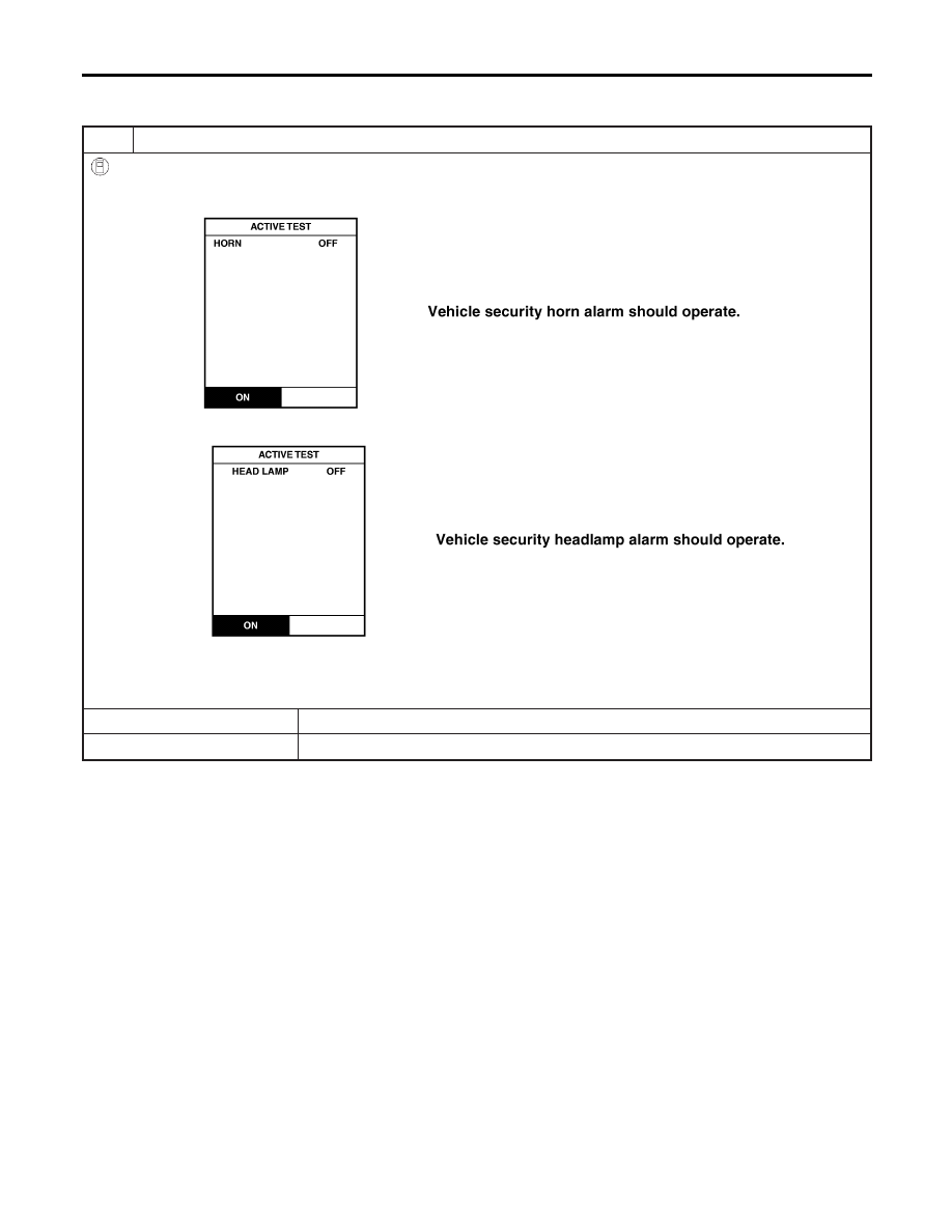
1. Select “ACTIVE TEST” in “THEFT WAR ALM” with CONSULT-II.
2. Select “HORN” and touch “ON”.
SEL041Y
3. Select “HEADLAMP” and touch “ON”.
SEL042Y
NOTE:
If CONSULT-II is not available, skip this procedure and go to the nest step.
OK or NG
OK
©
Vehicle security horn and headlamp alarm operation are OK.
NG
©
GO TO 2.
VEHICLE SECURITY (THEFT WARNING) SYSTEM
Trouble Diagnoses (Cont’d)
EL-358

2
CHECK VEHICLE SECURITY HORN AND HEADLAMP ALARM OPERATION WITHOUT CONSULT-II
Without CONSULT-II
1. Disconnect smart entrance control unit harness connector.
2. Apply ground to smart entrance control unit harness connector M144 terminal 42 (BR/Y).
SEL043YA
Refer to wiring diagram in EL-339.
3. Apply ground to smart entrance control unit harness connector M143 and M145 terminal 21 (OR) and 59 (P).
SEL198Y
Refer to wiring diagram in EL-340.
OK or NG
OK
©
Horn and headlamp alarm is OK.
NG
©
GO TO 3.
3
CHECK VEHICLE SECURITY HORN RELAYS
Check vehicle security horn relay-1 and relay-2.
OK or NG
OK
©
GO TO 4.
NG
©
Replace.
GI
MA
EM
LC
EC
FE
AT
AX
SU
BR
ST
RS
BT
HA
SC
IDX
VEHICLE SECURITY (THEFT WARNING) SYSTEM
Trouble Diagnoses (Cont’d)
EL-359

4
CHECK POWER SUPPLY FOR VEHICLE SECURITY HORN RELAYS
1. Disconnect vehicle security horn relay-1 and relay-2 connectors.
2. Check voltage between vehicle security horn relay-1 and relay-2 terminal 1 and ground.
SEL044Y
Does battery voltage exist?
Yes
©
GO TO 5.
No
©
Check the following.
I
10A fuse (No. 61 located in the fuse and fusible link box)
I
Harness for open or short between vehicle security horn relays and fuse
5
CHECK VEHICLE SECURITY HORN RELAYS CIRCUIT
1. Disconnect vehicle security horn relay-1 and relay-2 connectors.
2. Check voltage between vehicle security horn relay-1 and relay-2 terminals of each relay.
Battery voltage should exist.
SEL045Y
OK or NG
OK
©
Check harness for open or short between vehicle security horn relay-2 and headlamp
relays.
NG
©
Check the following.
I
Harness for open or short between vehicle security horn relay-1 and fuse
I
Harness for open or short between vehicle security horn relay-1 and relay-2
I
Harness for open or short between vehicle security horn relay-1 and vehicle security
horn
VEHICLE SECURITY (THEFT WARNING) SYSTEM
Trouble Diagnoses (Cont’d)
EL-360
Нет комментариевНе стесняйтесь поделиться с нами вашим ценным мнением.
Текст