Infiniti I35 (A33). Manual — part 418
CONSULT-II Application Items
NHEL0236
“RETAINED PWR”
NHEL0236S01
Data Monitor
NHEL0236S0101
Monitored Item
Description
IGN ON SW
Indicates [ON/OFF] condition of ignition switch.
DOOR SW-DR
Indicates [ON/OFF] condition of front door switch LH.
DOOR SW-AS
Indicates [ON/OFF] condition of front door switch RH.
Active Test
NHEL0236S0102
Test Item
Description
RETAINED PWR
This test is able to supply RAP signal (power) from smart entrance control unit to power window
system and power sunroof system. Those systems can be operated when turning on
“RETAINED PWR” on CONSULT-II screen even if the ignition switch is tuned OFF.
NOTE:
During this test, CONSULT-II can be operated with ignition switch in “OFF” position.
“RETAINED PWR” should be turned “ON” or “OFF” on CONSULT-II screen when ignition
switch is ON. Then turn ignition switch OFF to check retained power operation. CON-
SULT-II might be stuck if “RETAINED PWR” is turned “ON” or “OFF” on CONSULT-II
screen when ignition switch is OFF.
Work Support
NHEL0236S0103
Work Item
Description
RETAINED PWR SET
RAP signal’s power supply period can be changed by mode setting. Selects RAP signal’s
power supply period between two steps.
I
MODE 1 (45 sec.)/MODE 2 (OFF)/MODE 3 (2 min.)
Trouble Diagnoses
NHEL0105
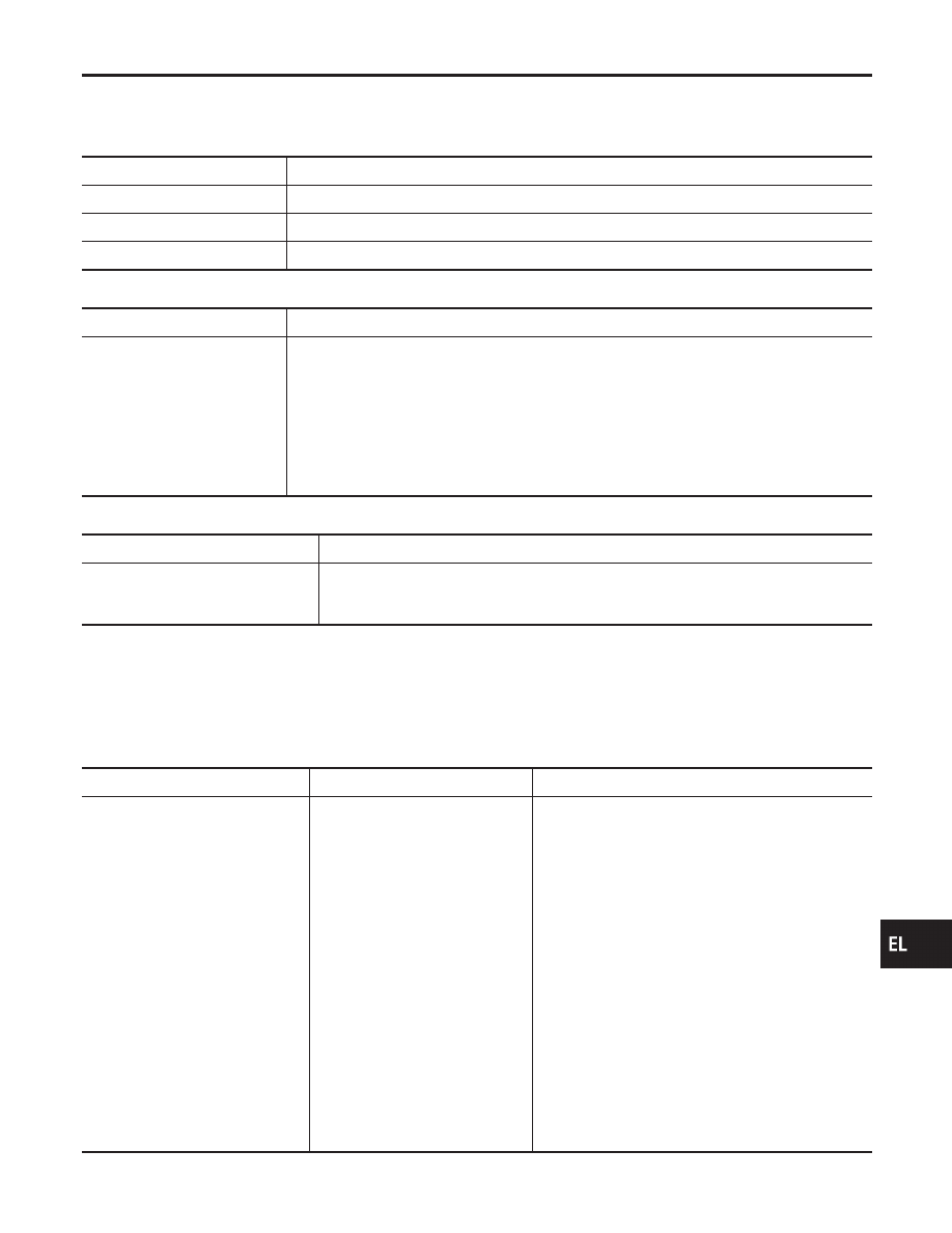
Symptom
Possible cause
Repair order
None of the power windows can be
operated using any switch.
1. 10A fuse, 40A fusible link
2. E90 circuit breaker
3. Power window relay
4. E90 circuit breaker circuit
5. Power window relay circuit
6. Ground circuit
7. Front power window main switch
1. Check 10A fuse [No. 10, located in fuse block
(J/B)], 40A fusible link (letter I, located in fuse and
fusible link box).
2. Check E90 circuit breaker.
3. Check power window relay.
4. Check the following.
a. Check harness between E90 circuit breaker and
40A fusible link (letter I, located in fuse and fusible
link box).
b. Check harness between E90 circuit breaker and
front power window main switch.
5. Check the following.
a. Check harness between E90 circuit breaker and
power window relay.
b. Check harness between fuse and power window
relay.
6. Check the following.
a. Check ground circuit of front power window main
switch terminal 5.
b. Check power window relay ground circuit.
7. Check front power window main switch.
GI
MA
EM
LC
EC
FE
AT
AX
SU
BR
ST
RS
BT
HA
SC
IDX
POWER WINDOW
CONSULT-II Application Items
EL-273
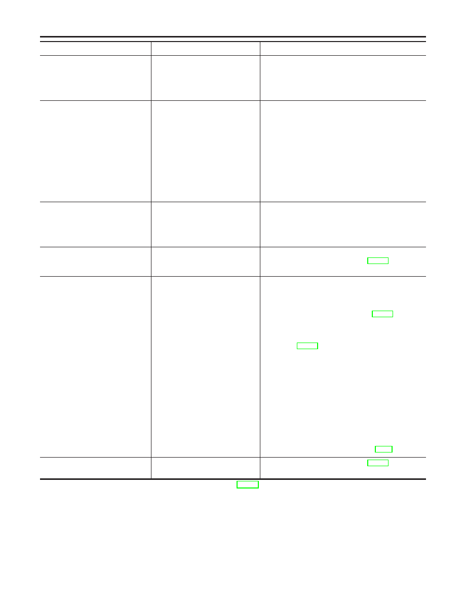
Symptom
Possible cause
Repair order
Driver side power window cannot
be operated but other windows can
be operated.
1. Driver side power window motor
circuit
2. Driver side power window motor
3. Front power window main switch
1. Check harness between front power window main
switch and driver side power window motor for
open or short circuit.
2. Check driver side power window motor.
3. Check front power window main switch.
One or more power windows
except driver’s side window cannot
be operated.
1. Power window switches
2. Power window motors
3. Power window main switch
4. Power window circuit
1. Check power window switch.
2. Check power window motor.
3. Check power window main switch.
4. Check the following.
a. Check harness between the rear power window
switch (LH and RH) terminal 5 and power window
relay terminal 5.
b. Check harnesses between power window main
switch and power window switch for open/short cir-
cuit.
c. Check harnesses between power window switch
and power window motor for open/short circuit.
Power windows except driver’s side
window cannot be operated using
power window main switch but can
be operated by power window
switch.
1. Power window main switch
1. Check front power window main switch.
Driver side power window auto-
matic operation does not function
properly.
1. Front power window main switch
2. Encoder and limit switch
1. Check front power window main switch.
2. Check encoder and limit switch. (EL-275)
Retained power operation does not
operate properly.
1. RAP signal circuit
2. Driver or passenger side door
switch circuit
3. Smart entrance control unit
1. Check RAP signal.
a. (With CONSULT-II)
I
Check RAP signal with CONSULT-II.
Use “WORK SUPPORT” mode, “RETAINED PWR”
in “SMART ENTRANCE”. (Refer to EL-272.)
I
Check RAP signal with CONSULT-II.
Use “ACTIVE TEST” mode, “RETAINED PWR” in
“SMART ENTRANCE”.
(Refer to EL-272.)
If NG, go to the step b. below.
b. Verify 12 positive voltage from smart entrance con-
trol unit is present at terminal 2 of power window
relay:
I
Within 45 seconds after ignition switch turns off.*1
I
When front door LH and RH is closed.
2. Check harness between smart entrance control unit
and driver or passenger side door switch for short
circuit.
Check driver or passenger side door switch ground
circuit.
Check driver or passenger side door switch.
3. Check smart entrance control unit. (EL-52)
Interruption detection function does
not operate properly.
1. Encoder and limit switch
1. Check encoder and limit switch. (EL-275)
NOTE: *1 RAP signal’s period can be changed by CONSULT-II. (EL-273)
POWER WINDOW
Trouble Diagnoses (Cont’d)
EL-274
ENCODER AND LIMIT SWITCH CHECK
=NHEL0105S01
1
CHECK DOOR WINDOW SLIDE MECHANISM
Check the following.
I
Obstacles in window, glass molding, etc.
I
Worn or deformed glass molding
I
Door sash tilted too far inward or outward
I
Door window motor
OK or NG
OK
©
GO TO 2.
NG
©
Remove obstacles or repair door window slide mechanism.
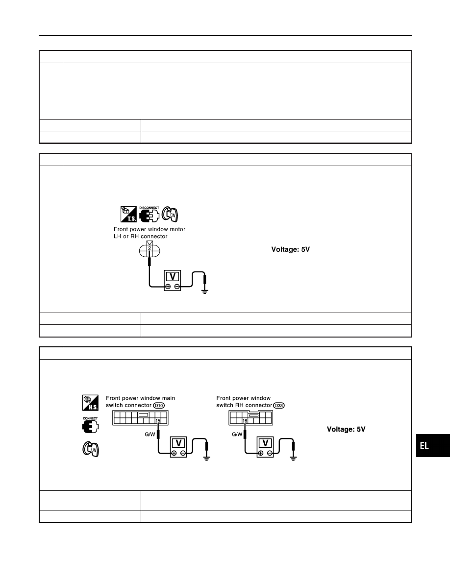
2
CHECK LIMIT SWITCH POWER SUPPLY INPUT SIGNAL
1. Disconnect front power window motor LH or RH connector.
2. Turn ignition switch to ON position.
3. Check voltage between front power window motor LH harness connector D4 terminal 2 (G/W) or front power window
motor RH harness connector D38 terminal 2 (G/W) and ground.
SEL835YA
OK or NG
OK
©
GO TO 4.
NG
©
GO TO 3.
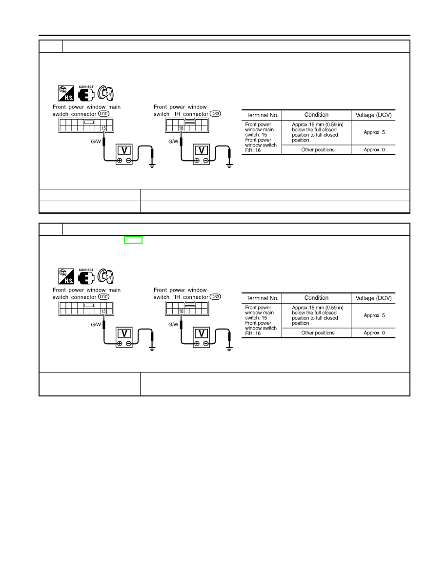
3
CHECK LIMIT SWITCH POWER SUPPLY OUTPUT SIGNAL
Check voltage between front power window main switch terminal 15 or front power window switch RH terminal 16 and
ground.
SEL725WB
OK or NG
OK
©
Repair harness or connectors between power window switch and front power window
motor.
NG
©
Replace power window main switch or front power window switch RH.
GI
MA
EM
LC
EC
FE
AT
AX
SU
BR
ST
RS
BT
HA
SC
IDX
POWER WINDOW
Trouble Diagnoses (Cont’d)
EL-275
4
CHECK LIMIT SWITCH OPERATION
1. Connect front power window motor LH or RH connector.
2. Check voltage between front power window main switch terminal 15 or front power window switch RH terminal 16 and
ground during power window closing operation.
SEL726W
OK or NG
OK
©
GO TO 7.
NG
©
GO TO 5.
5
RESET LIMIT SWITCH
Reset limit switch. Refer to BT-23, “Front Door Glass Limit Switch Reset”. Then check voltage between front power win-
dow main switch terminal 15 or front power window switch RH terminal 16 and ground during power window closing
operation at least ten times.
SEL726W
OK or NG
OK
©
INSPECTION END
NG
©
GO TO 6.
POWER WINDOW
Trouble Diagnoses (Cont’d)
EL-276
Нет комментариевНе стесняйтесь поделиться с нами вашим ценным мнением.
Текст