Infiniti I35 (A33). Manual — part 44
Possible Cause
NHAT0232
Check the following items.
I
Harness or connectors
(The solenoid circuit is open or shorted.)
I
Line pressure solenoid valve
SAT014K
SEF949Y
Diagnostic Trouble Code (DTC) Confirmation
Procedure
NHAT0233
NOTE:
If “DTC Confirmation Procedure” has been previously conducted,
always turn ignition switch OFF and wait at least 10 seconds before
conducting the next test.
After the repair, perform the following procedure to confirm the
malfunction is eliminated.
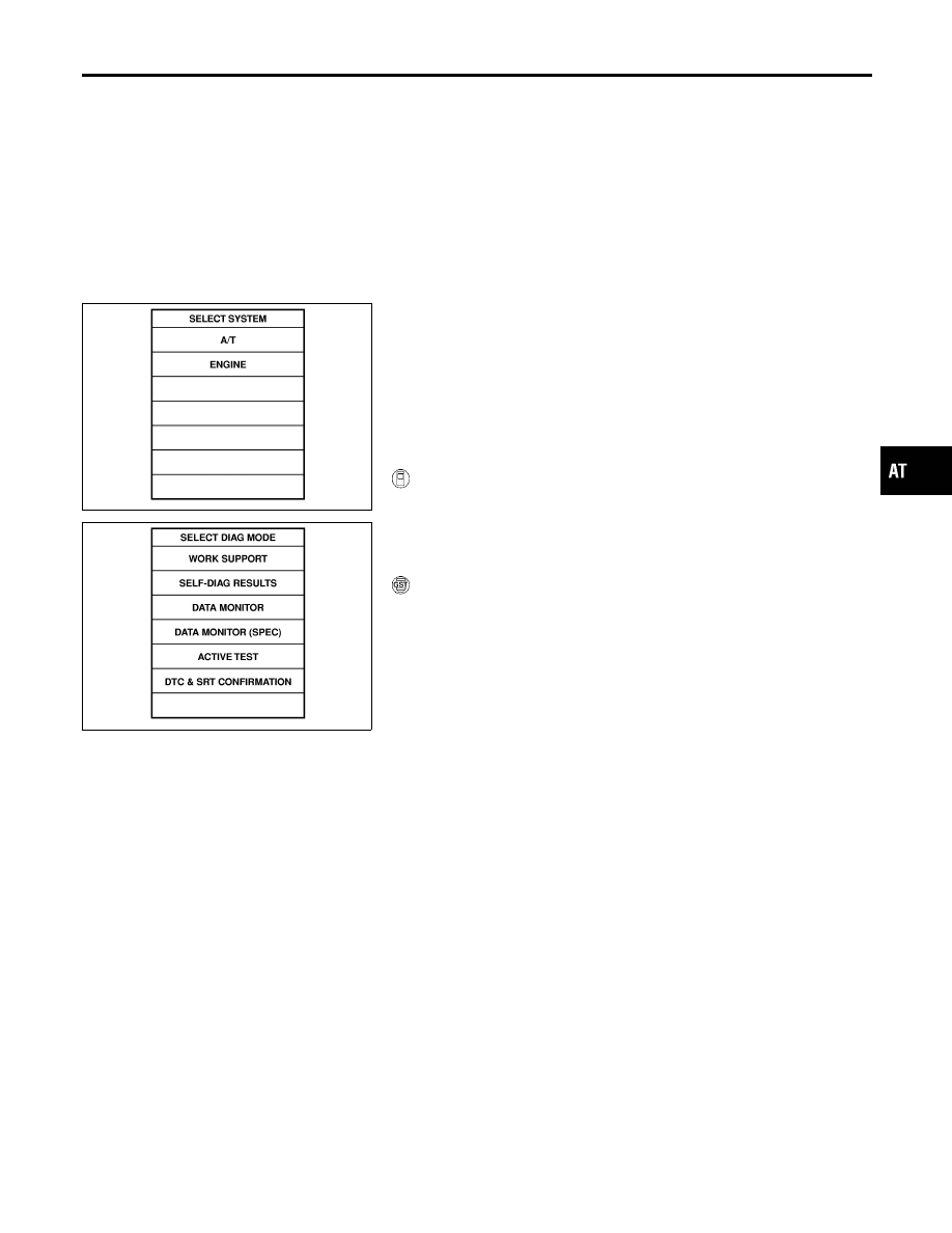
WITH CONSULT-II
NHAT0233S01
1)
Turn ignition switch ON and select “DATA MONITOR” mode for
“ENGINE” with CONSULT-II.
2)
Depress accelerator pedal completely and wait at least 5 sec-
onds.
WITH GST
NHAT0233S02
Follow the procedure “With CONSULT-II”.
GI
MA
EM
LC
EC
FE
AX
SU
BR
ST
RS
BT
HA
SC
EL
IDX
DTC P0745 LINE PRESSURE SOLENOID VALVE
Possible Cause
AT-173
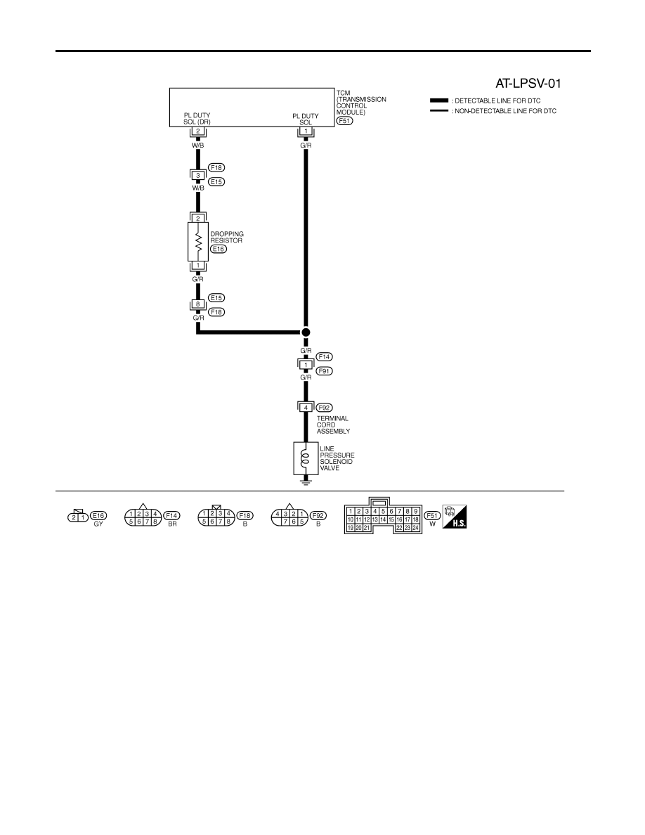
Wiring Diagram — AT — LPSV
NHAT0065
MAT482B
DTC P0745 LINE PRESSURE SOLENOID VALVE
Wiring Diagram — AT — LPSV
AT-174
Diagnostic Procedure
NHAT0066
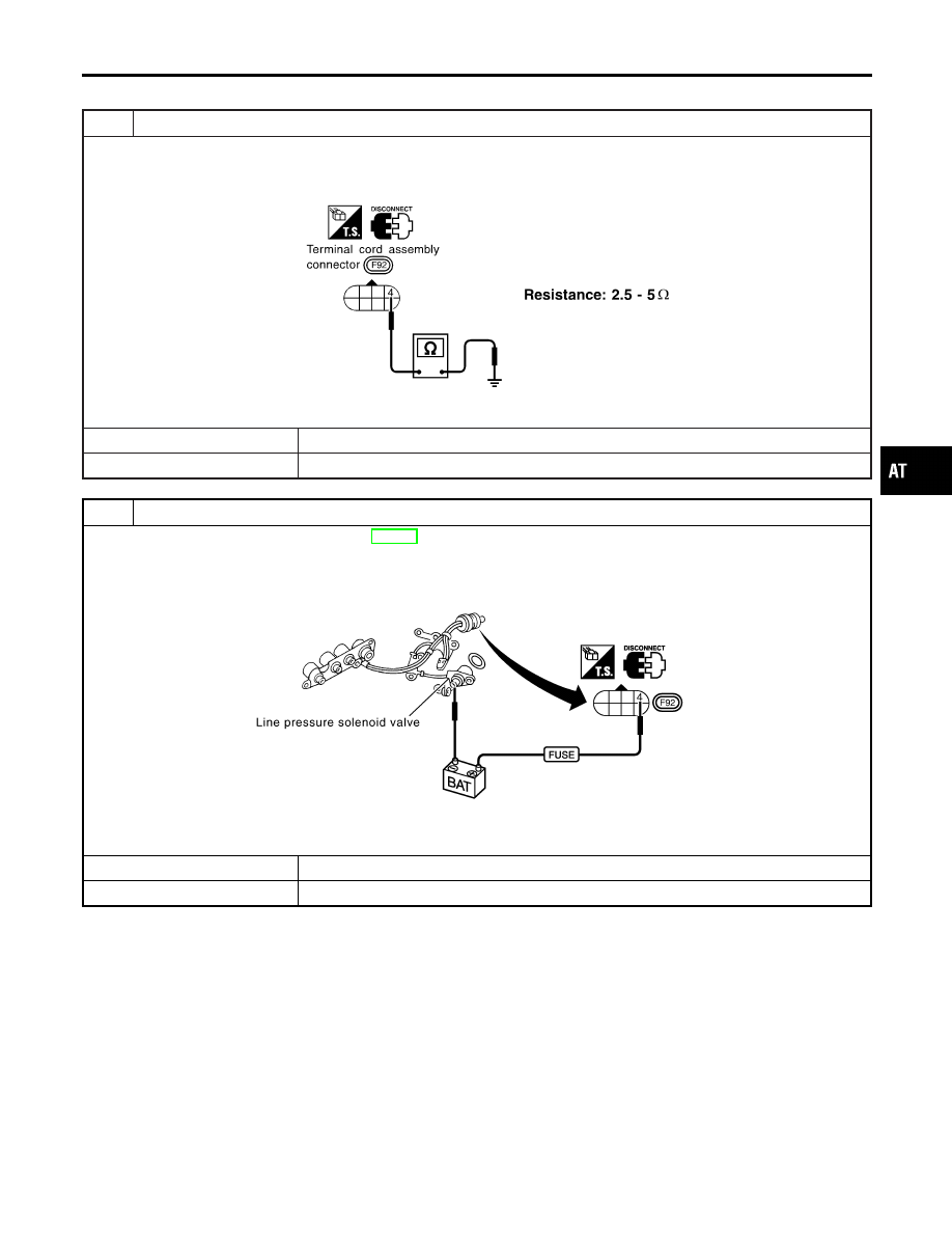
1
CHECK SOLENOID VALVE RESISTANCE
1. Turn ignition switch to OFF position.
2. Disconnect terminal cord assembly connector in engine compartment.
3. Check resistance between terminal 4 (G/R) and ground.
SAT630JB
OK or NG
OK
©
GO TO 3.
NG
©
GO TO 2.
2
CHECK SOLENOID VALVE OPERATION
1. Remove control valve assembly. Refer to AT-282.
2. Check the following items:
I
Line pressure solenoid valve
i. Check solenoid valve by listening for its operating sound while applying battery voltage to the terminal and ground.
SAT830K
I
Harness of terminal cord assembly for short or open
OK or NG
OK
©
GO TO 3.
NG
©
Repair or replace damaged parts.
GI
MA
EM
LC
EC
FE
AX
SU
BR
ST
RS
BT
HA
SC
EL
IDX
DTC P0745 LINE PRESSURE SOLENOID VALVE
Diagnostic Procedure
AT-175
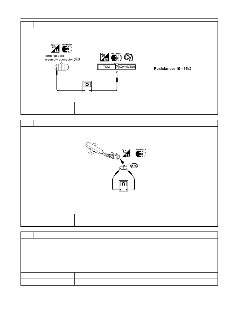
3
CHECK POWER SOURCE AND DROPPING RESISTOR CIRCUIT
1. Turn ignition switch to OFF position.
2. Disconnect TCM harness connector.
3. Check resistance between terminal 4 (G/R) and TCM harness connector F51 terminal 2 (W/B).
SAT631JF
OK or NG
OK
©
GO TO 5.
NG
©
GO TO 4.
4
DETECT MALFUNCTIONING ITEM
Check the following items:
I
Dropping resistor
I
Check resistance between two terminals.
SAT933IB
Resistance:
12
Ω
(Approx.)
I
Harness for short or open between TCM harness connector F50 terminal 2 (W/B) and terminal cord assembly
OK or NG
OK
©
GO TO 5.
NG
©
Repair or replace damaged parts.
5
CHECK POWER SOURCE CIRCUIT
1. Turn ignition switch to OFF position.
2. Check continuity between terminal cord assembly connector terminal 4 (G/R) and TCM harness connector F50 terminal
1 (G/R). Refer to wiring diagram — AT — LPSV.
Continuity should exist.
If OK, check harness for short to ground and short to power.
3. Reinstall any part removed.
OK or NG
OK
©
GO TO 6.
NG
©
Repair open circuit or short to ground or short to power in harness or connectors.
DTC P0745 LINE PRESSURE SOLENOID VALVE
Diagnostic Procedure (Cont’d)
AT-176
Нет комментариевНе стесняйтесь поделиться с нами вашим ценным мнением.
Текст