Infiniti I35 (A33). Manual — part 598
SST869C
I
After installing gear in vehicle, make sure that the clinched
section of boot band is positioned toward the rear of vehicle (to
prevent interference with adjacent parts).
SST719C
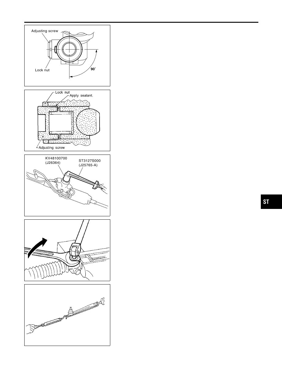
Adjustment
NHST0026
Adjust pinion rotating torque as follows:
1.
Set rack to the neutral position without fluid in the gear.
2.
Coat the adjusting screw with locking sealant and screw it in.
3.
Lightly tighten lock nut.
4.
Tighten adjusting screw to a torque of 4.9 to 5.9 N·m (50 to 60
kg-cm, 43 to 52 in-lb).
5.
Loosen adjusting screw, then retighten it to 0.2 N·m (2 kg-cm,
1.7 in-lb).
SST862C
6.
Move rack over its entire stroke several times.
7.
Measure pinion rotating torque within the range of 180° from
neutral position.
Stop the gear at the point of maximum torque.
8.
Loosen adjusting screw, then retighten it to 4.9 N·m (50 kg-cm,
43 in-lb).
9.
Loosen adjusting screw by 60° to 80°.
SST713C
10. Prevent adjusting screw from turning, and tighten lock nut to
specified torque.
SST090B
11. Check rack sliding force on vehicle as follows:
a.
Install steering gear onto vehicle, but do not connect tie-rod to
knuckle arm.
b.
Connect all piping and fill with steering fluid.
c.
Start engine and bleed air completely.
d.
Disconnect steering column lower joint from the gear.
e.
Keep engine at idle and make sure steering fluid has reached
normal operating temperature.
f.
Pull tie-rod slowly to move it from neutral position to
±
11.5 mm
(
±
0.453 in) at speed of 3.5 mm (0.138 in)/s. Check that rack
sliding force is within specification.
GI
MA
EM
LC
EC
FE
AT
AX
SU
BR
RS
BT
HA
SC
EL
IDX
POWER STEERING GEAR AND LINKAGE
Assembly (Cont’d)
ST-23
Average rack sliding force:
216 - 284 N (22 - 29 kg, 49 - 64 lb)
Maximum force deviation:
98 N (10 kg, 22 lb)
g.
Check sliding force outside above range at rack speed of 40
mm (1.57 in)/s.
Maximum rack sliding force:
294 N (30 kg, 66 lb)
Maximum force deviation:
147 N (15 kg, 33 lb)
I
If rack sliding force is not within specification, readjust by
repeating adjustment procedure from the beginning.
I
If rack sliding force is still out of specification after
readjustment, gear assembly needs to be replaced.
POWER STEERING GEAR AND LINKAGE
Adjustment (Cont’d)
ST-24
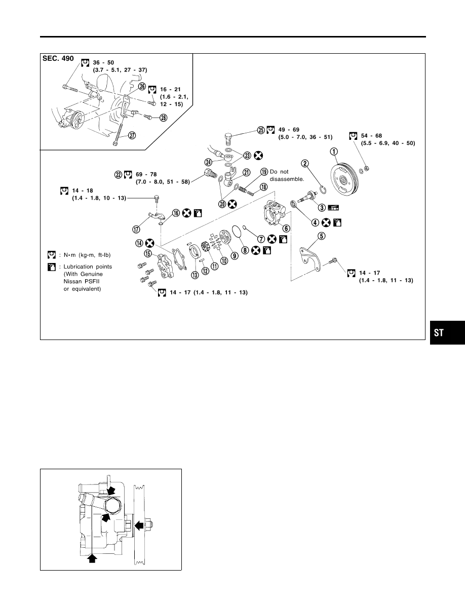
Components
NHST0027
SST870C
1.
Pulley
2.
Snap ring
3.
Drive shaft
4.
Oil seal
5.
Bracket
6.
Front housing
7.
O-ring
8.
O-ring
9.
Front side plate
10. Vane
11. Rotor
12. Pin
13. Cam ring
14. Gasket
15. Rear housing
16. O-ring
17. Suction pipe
18. Spring
19. Flow control valve
20. Washer
21. Joint
22. Connector
23. Washer
24. Hose
25. Connector bolt
26. Adjusting bracket
27. Adjusting bolt
28. Lock bolt
SST984A
Pre-disassembly Inspection
NHST0028
Disassemble the power steering oil pump only if the following items
are found.
I
Oil leak from any point shown in the figure
I
Deformed or damaged pulley
I
Poor performance
GI
MA
EM
LC
EC
FE
AT
AX
SU
BR
RS
BT
HA
SC
EL
IDX
POWER STEERING OIL PUMP
Components
ST-25
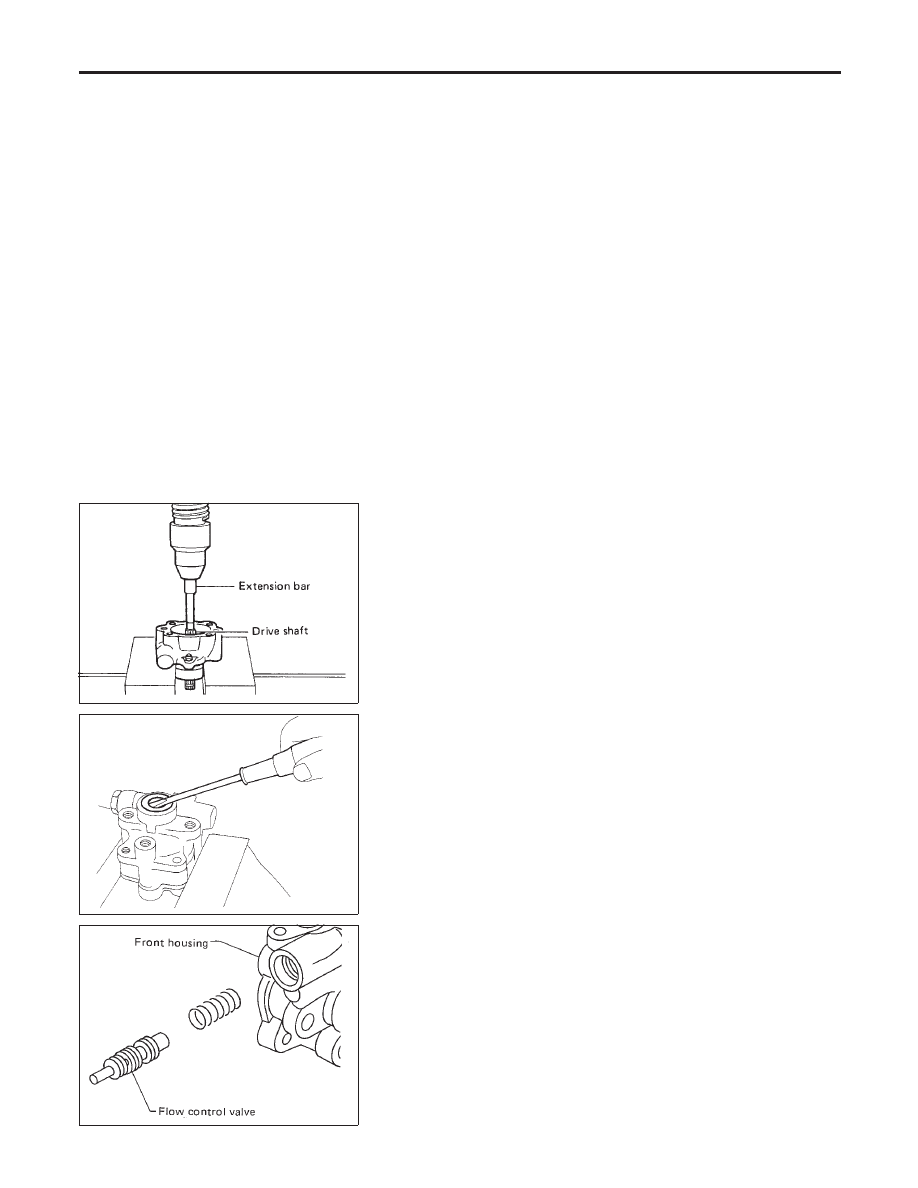
Disassembly
NHST0029
CAUTION:
I
Parts which can be disassembled are strictly limited.
Never disassemble parts other than those specified.
I
Disassemble in as clean a place as possible.
I
Clean your hands before disassembly.
I
Do not use rags; use nylon cloths or paper towels.
I
Follow the procedures and cautions in the Service
Manual.
I
When disassembling and reassembling, do not let foreign
matter enter or contact the parts.
SST010B
I
Remove snap ring, then draw drive shaft out.
Be careful not to drop drive shaft.
SST034A
I
Remove oil seal.
Be careful not to damage front housing.
SST036A
I
Remove connector and flow control valve with spring.
Be careful not to drop flow control valve.
Do not disassemble flow control valve.
POWER STEERING OIL PUMP
Disassembly
ST-26
Нет комментариевНе стесняйтесь поделиться с нами вашим ценным мнением.
Текст