Infiniti G37 Coupe. Manual — part 335
CL-12
< ON-VEHICLE REPAIR >
CLUTCH MASTER CYLINDER
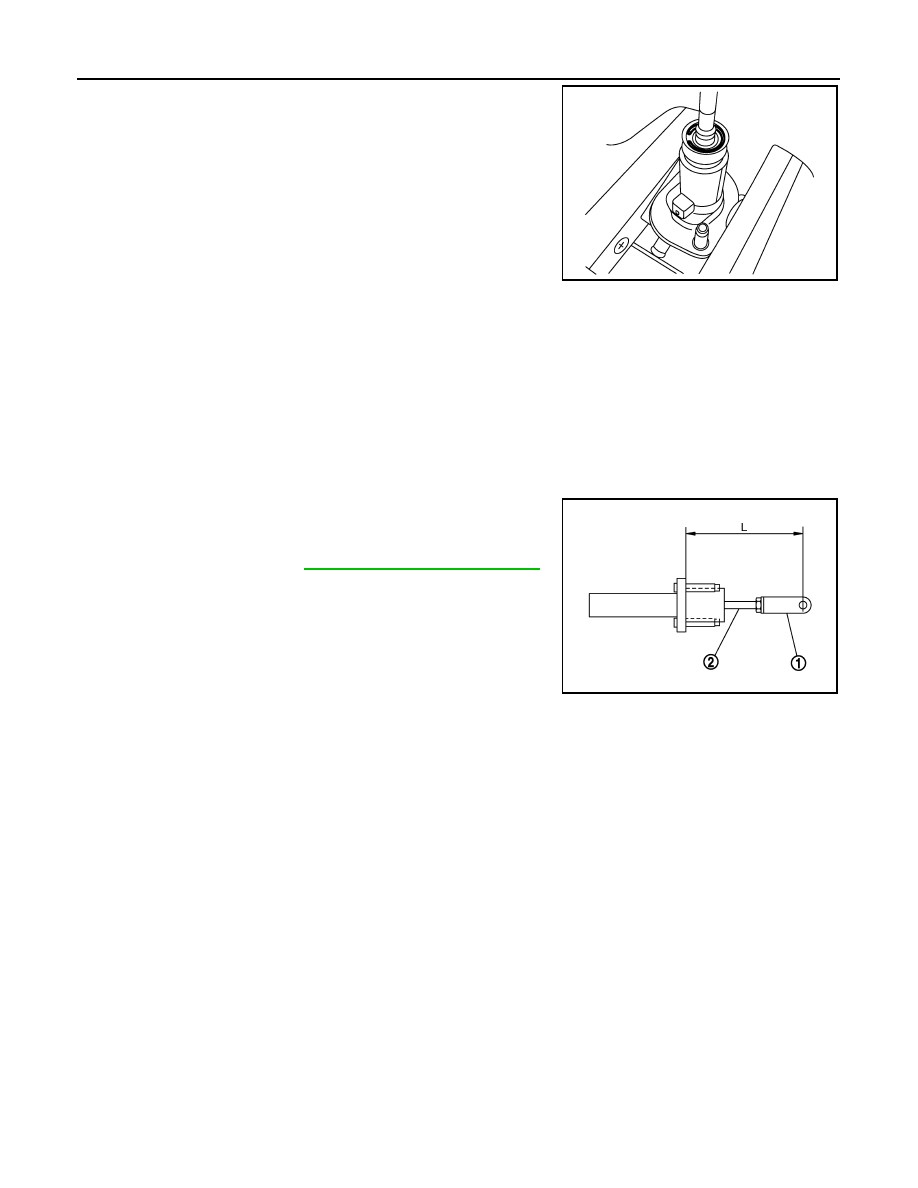
3.
Remove stopper ring.
4.
Remove push rod while holding it securely to prevent piston
assembly popping out.
5.
Remove piston assembly and return spring.
ASSEMBLY
1.
Apply rubber lubricant to the internal surface of cylinder body, the sliding surface and piston cup of piston
assembly.
2.
Insert return spring and piston assembly to cylinder body.
3.
Apply silicon grease to push rod.
4.
Install stopper ring while holding down push rod by hand to prevent piston assembly from popping out.
CAUTION:
Never reuse stopper ring.
5.
Install boot to cylinder body.
6.
Install lock nut and clevis to push rod.
7.
Check and adjust the positions of clevis (1) and push rod (2).
After adjusting length, tighten lock nut to the specified torque.
Inspection
INFOID:0000000001731692
INSPECTION AFTER DISASSEMBLY
Check for any of the conditions shown below. If any malfunction is found, replace the part concerned.
• Damaged cylinder internal wall, foreign matter, wear, corrosion.
• Damaged or deformed reservoir tank.
• Settling of return spring.
• Cracked or deformed boot.
• Cracked or deformed packing.
JPDIB0013ZZ
Length “L”
: Refer to
CL-22, "Clutch Master Cylinder"
.
JPDIB0014ZZ
CLUTCH PIPING
CL-13
< ON-VEHICLE REPAIR >
C
E
F
G
H
I
J
K
L
M
A
B
CL
N
O
P
CLUTCH PIPING
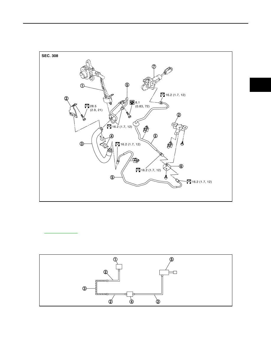
Exploded View
INFOID:0000000001731693
Hydraulic Layout
INFOID:0000000001731694
1.
CSC (Concentric Slave Cylinder) as-
sembly
2.
Bracket
3.
Clutch hose
4.
Lock plate
5.
Clutch tube
6.
Connector
7.
Master cylinder assembly
Refer to
for the symbols in the figure.
JPDIB0088GB
1.
CSC (Concentric Slave Cylinder) as-
sembly
2.
Clutch tube
3.
Clutch hose
4.
Connector
5.
Master cylinder assembly
JPDIB0016ZZ
CL-14
< ON-VEHICLE REPAIR >
CLUTCH PIPING
Removal and Installation
INFOID:0000000001731695
CAUTION:
Keep painted surface on the body or other parts free of clutch fluid. If it spills, wipe up immediately
and wash the affected area with water.
REMOVAL
Refer to the figure for removal procedure.
INSTALLATION
Refer to the figure for installation procedure.
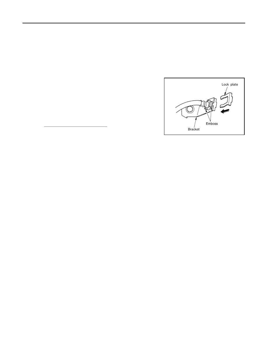
• To fix clutch hose on bracket, position clutch hose clasp on the
emboss of bracket and drive lock plate vertically from above.
CAUTION:
• Never bend or twist clutch hose.
• Never scratch or damage clutch hose.
• Tighten clutch tube flare nut to the specified torque.
CAUTION:
Never damage flare nut and clutch tube.
• After installation, bleed the air from the clutch hydraulic system.
CL-6, "Air Bleeding Procedure"
PCIB0681E
CSC (CONCENTRIC SLAVE CYLINDER)
CL-15
< REMOVAL AND INSTALLATION >
C
E
F
G
H
I
J
K
L
M
A
B
CL
N
O
P
REMOVAL AND INSTALLATION
CSC (CONCENTRIC SLAVE CYLINDER)
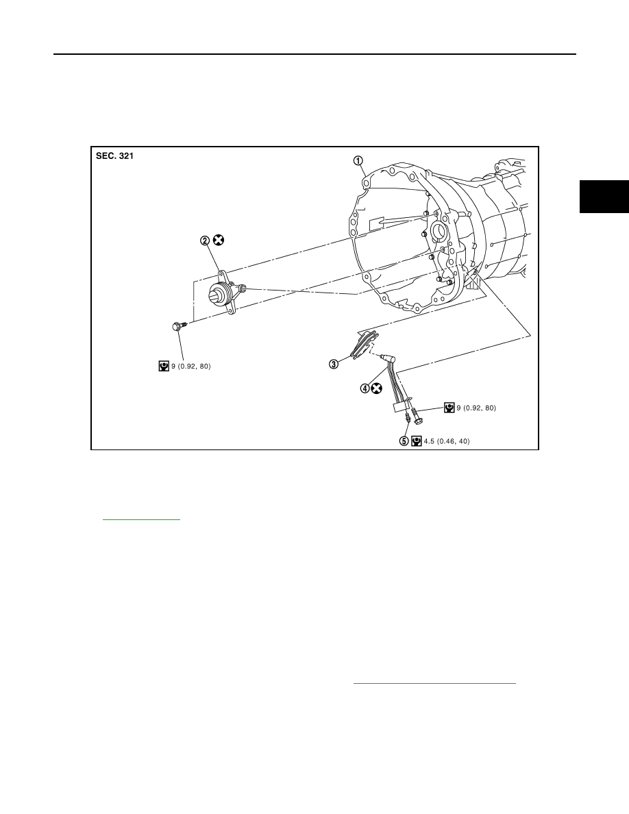
Exploded View
INFOID:0000000001731696
Removal and Installation
INFOID:0000000001731697
CAUTION:
• If transmission assembly is removed from the vehicle, always replace CSC (Concentric Slave Cylin-
der) body and CSC tube. Return CSC body insert to original position to remove transmission assem-
bly. Dust on clutch disc sliding parts may damage seal of CSC body and may cause clutch fluid
leakage.
• Never disassemble CSC body.
• Keep painted surface on the body or other parts free of clutch fluid. If it spills, wipe up immediately
and wash the affected area with water.
REMOVAL
1.
Remove transmission assembly from the vehicle. Refer to
TM-25, "Removal and Installation"
JPDIB0018GB
1.
Transmission assembly
2.
CSC (Concentric Slave Cylinder)
body
3.
Dust cover
4.
CSC (Concentric Slave Cylinder)
tube
5.
Air bleeder valve
Refer to
Нет комментариевНе стесняйтесь поделиться с нами вашим ценным мнением.
Текст