Infiniti G37 Coupe. Manual — part 608
PRECAUTIONS
EM-7
< PRECAUTION >
C
D
E
F
G
H
I
J
K
L
M
A
EM
N
P
O
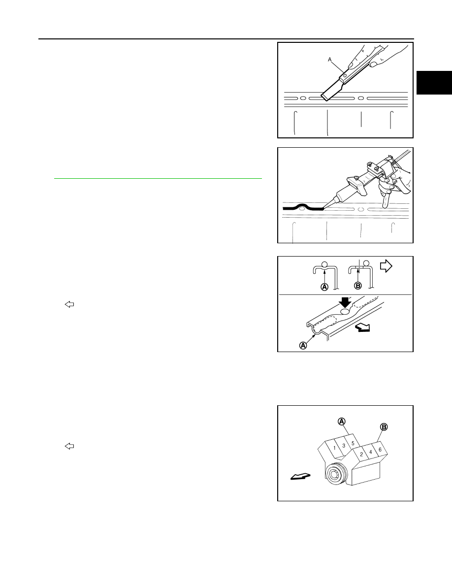
1.
Using a scraper (A), remove old liquid gasket adhering to the liq-
uid gasket application surface and the mating surface.
• Remove liquid gasket completely from the groove of the liquid
gasket application surface, mounting bolts and bolt holes.
2.
Wipe the liquid gasket application surface and the mating sur-
face with white gasoline (lighting and heating use) to remove
adhering moisture, grease and foreign materials.
3.
Attach liquid gasket tube to the tube presser (commercial ser-
vice tool).
Use Genuine RTV Silicone Sealant or equivalent. Refer to
GI-15, "Recommended Chemical Products and Sealants"
.
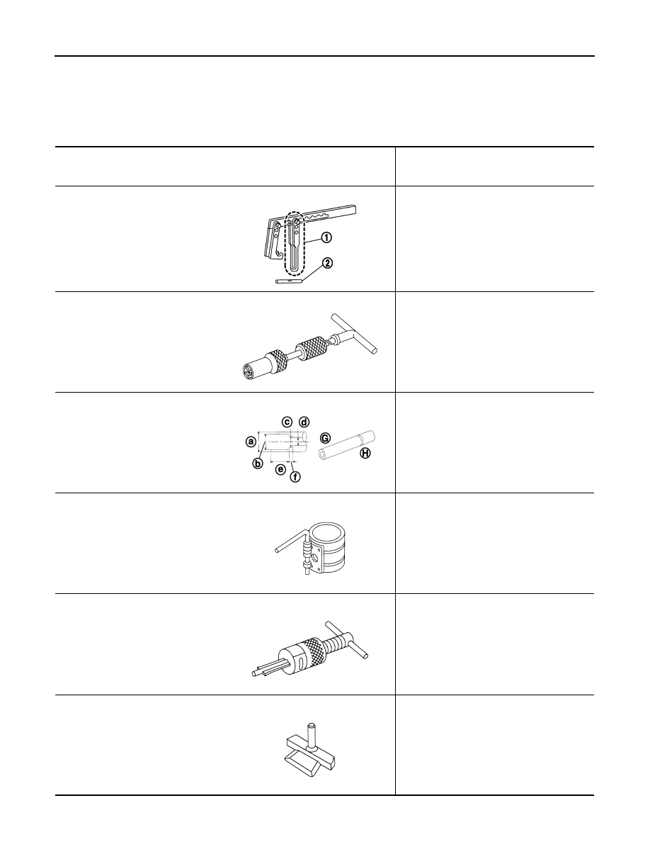
4.
Apply liquid gasket without gaps to the specified location accord-
ing to the specified dimensions.
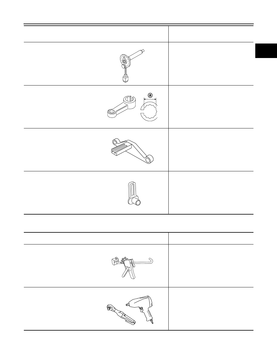
• If there is a groove for liquid gasket application, apply liquid
gasket to the groove.
• As for bolt holes (B), normally apply liquid gasket inside the
holes. Occasionally, it should be applied outside the holes.
Make sure to read the text of this manual.
• Within five minutes of liquid gasket application, install the mat-
ing component.
• If liquid gasket protrudes, wipe it off immediately.
• Do not retighten mounting bolts or nuts after the installation.
• After 30 minutes or more have passed from the installation, fill
engine oil and engine coolant.
CAUTION:
If there are specific instructions in this manual, observe them.
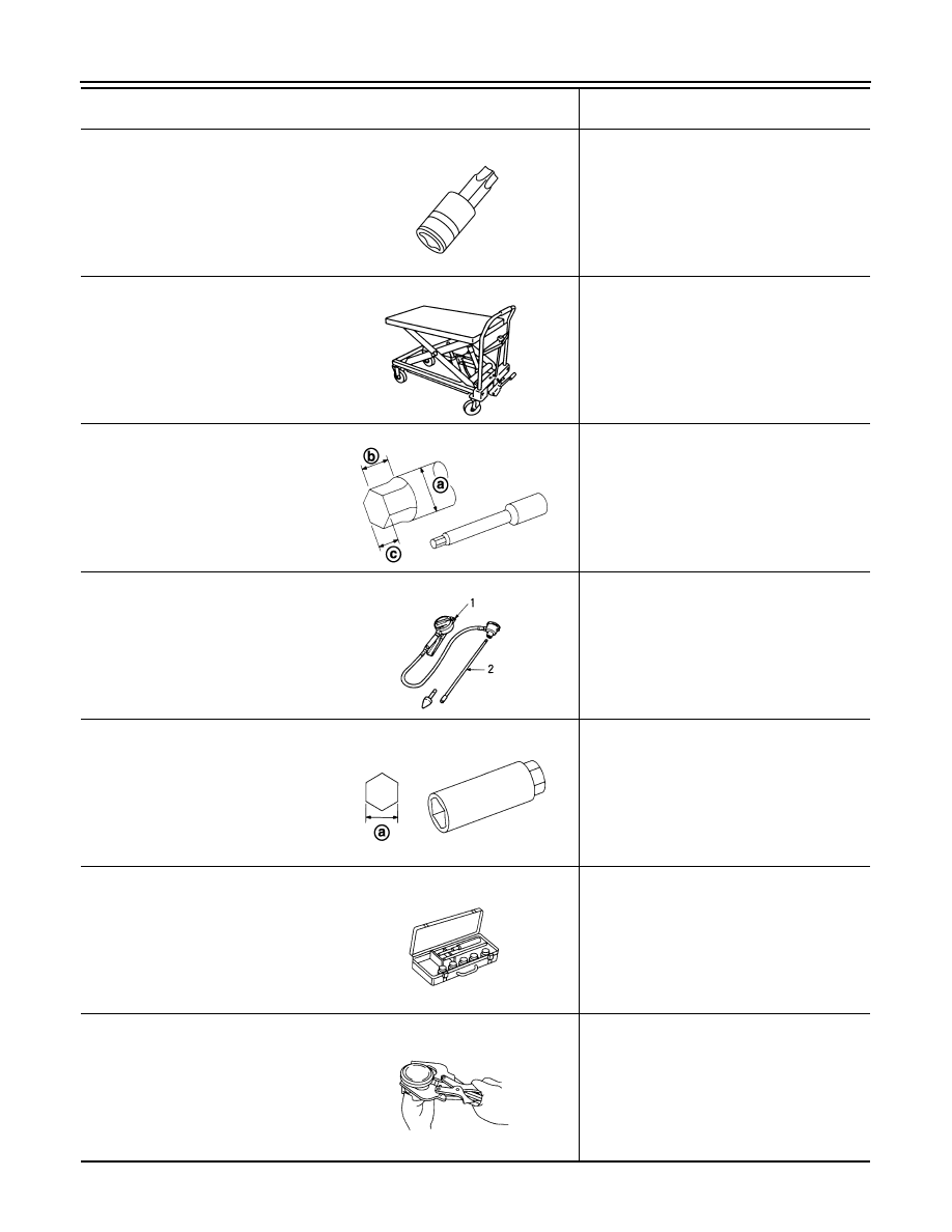
Definitions of Bank Names
INFOID:0000000001674979
• In this manual, each bank name is defined as follows:
• For cylinder numbers and bank layout, refer to the illustration.
JPBIA0053ZZ
EMA0622D
A
: Groove
: Inside
JPBIA0010ZZ
A
: Bank 1 (The conventional right bank)
B
: Bank 2 (The conventional left bank)
: Engine front
Bank 1
: The bank side including cylinder No. 1
(odd-numbered cylinder side)
Bank 2
: The other bank side of the above
(even-numbered cylinder side)
JPBIA1135ZZ
EM-8
< PREPARATION >
PREPARATION
PREPARATION
PREPARATION
Special Service Tools
INFOID:0000000001547620
The actual shapes of Kent-Moore tools may differ from those of special service tools illustrated here.
Tool number
(Kent-Moore No.)
Tool name
Description
KV10116200
(J26336-A)
Valve spring compressor
1. KV10115900
(J26336-20)
Attachment
2.KV10109220
(
—
)
Adapter
Disassembling valve mechanism
Part (1) is a component of KV10116200
(J26336-A), but Part (2) is not so.
KV10107902
(J38959)
Valve oil seal puller
Replacing valve oil seal
KV10115600
(J-38958)
Valve oil seal drift
Installing valve oil seal
Use side A (G).
a: 20 (0.79) dia. d: 8 (0.31) dia.
b: 13 (0.51) dia. e: 10.7 (0.421)
c: 10.3 (0.406) dia. f: 5 (0.20)
H: side B
Unit: mm (in)
EM03470000
(J8037)
Piston ring compressor
Installing piston assembly into cylinder bore
ST16610001
(J23907)
Pilot bushing puller
Removing pilot converter
KV10111100
(J37228)
Seal cutter
Removing oil pan (lower and upper), front and
rear timing chain case, etc.
PBIC1650E
NT011
JPBIA0396ZZ
NT044
NT045
NT046
PREPARATION
EM-9
< PREPARATION >
C
D
E
F
G
H
I
J
K
L
M
A
EM
N
P
O
Commercial Service Tools
INFOID:0000000001547621
KV10112100
(BT8653-A)
Angle wrench
Tightening bolts for connecting rod bearing
cap, cylinder head, etc. at an angle
KV10114400
(J38365)
Heated oxygen sensor wrench
Loosening or tightening air fuel ratio sensor 1
a: 22 mm (0.87 in)
KV10118600
(J-48641)
Ring gear stopper
Removing and installing crankshaft pulley
—
(J-45488)
Quick connector release
Removing fuel tube quick connectors in en-
gine room
Tool number
(Kent-Moore No.)
Tool name
Description
NT014
JPBIA0397ZZ
JPBIA0409ZZ
PBIC0198E
(Kent-Moore No.)
Tool name
Description
(
—
)
Tube presser
Pressing the tube of liquid gasket
(
—
)
Power tool
Loosening nuts and bolts
NT052
PBIC0190E
EM-10
< PREPARATION >
PREPARATION
(
—
)
TORX socket
Removing and installing drive plate
(
—
)
Manual lift table caddy
Removing and installing engine
(J24239-01)
Cylinder head bolt wrench
Loosening and tightening cylinder head bolt,
and used with the angle wrench [SST:
KV10112100 (BT8653-A)]
a: 13 (0.51) dia.
b: 12 (0.47)
c: 10 (0.39)
Unit: mm (in)
(
—
)
1.Compression gauge
2.Adapter
Checking compression pressure
(
—
)
Spark plug wrench
Removing and installing spark plug
a: 14 mm (0.55 in)
(
—
)
Valve seat cutter set
Finishing valve seat (EXH) dimensions
(
—
)
Piston ring expander
Removing and installing piston ring
(Kent-Moore No.)
Tool name
Description
PBIC1113E
ZZA1210D
JPBIA0398ZZ
ZZA0008D
JPBIA0399ZZ
NT048
NT030
Нет комментариевНе стесняйтесь поделиться с нами вашим ценным мнением.
Текст