Infiniti G37 Coupe. Manual — part 662
EXL-68
< COMPONENT DIAGNOSIS >
[XENON TYPE]
XENON HEADLAMP
XENON HEADLAMP
Description
INFOID:0000000001604661
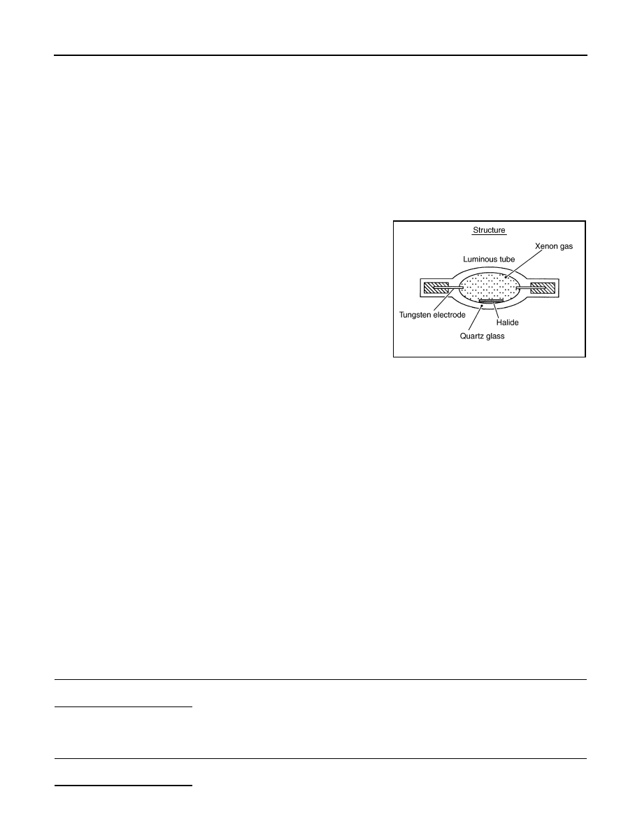
OUTLINE
• The lamp light source is by the arch discharge by applying high voltage into the xenon gas-filled bulb instead
of the halogen bulb filament.
• Sight becomes more natural and brighter because the amount of light are gained adequately and the color of
light is sunshine-like white.
• The xenon bulb drops the amount of light, repeats blinking, and illuminates in red if the bulb reaches the ser-
vice life.
ILLUMINATION PRINCIPLE
1.
Discharging starts in high voltage pulse between bulb elec-
trodes.
2.
Xenon gas is activated by current between electrodes. Pale light
is emitted.
3.
The luminous tube (bulb) temperature elevates. Evaporated
halide is activated by discharge. The color of light changes into
white.
NOTE:
• Brightness and the color of light may change slightly immediately
after the headlamp turned ON until the xenon bulb becomes sta-
ble. This is not malfunction.
• Illumination time lag may occur between right and left. This is not
malfunction.
PRECAUTIONS FOR TROUBLE DIAGNOSIS
Representative malfunction examples are; "Light does not turn ON", "Light blinks", and "Brightness is inade-
quate." The cause often be the xenon bulb. Such malfunctions, however, are occurred occasionally by HID
control unit malfunction or lamp case malfunction. Specify the malfunctioning part with diagnosis procedure.
WARNING:
• Never touch the harness, HID control unit, the inside and metal part of lamp when turning the head-
lamp ON or operating the light switch.
• Never work with wet hands.
CAUTION:
• Never perform HID control unit circuit diagnosis with a circuit tester or an equivalent.
• Temporarily install the headlamp on the vehicle. Connect the battery to the connector (vehicle side)
when checking ON/OFF status.
• Disconnect the battery negative terminal before disconnecting the lamp socket connector or the har-
ness connector.
• Check for fusing of the fusible link(s), open around connector, short, disconnection if the symptom
is caused by electric error.
NOTE:
• Turn the switch OFF once before turning ON, if the ON/OFF is inoperative.
• The xenon bulb drops the amount of light, repeats blinking, and illuminates in red if the bulb reaches the ser-
vice life.
Diagnosis Procedure
INFOID:0000000001604662
1.
CHECK XENON BULB
Install the normal bulb to the applicable headlamp. Check that the xenon bulb is turned ON.
Is the headlamp turned ON?
YES
>> Replace the xenon bulb.
NO
>> GO TO 2.
2.
CHECK HID CONTROL UNIT
Install the normal HID control unit to the applicable headlamp. Check that the lamp is turned ON.
Is the headlamp turned ON?
JPLIA0421GB
XENON HEADLAMP
EXL-69
< COMPONENT DIAGNOSIS >
[XENON TYPE]
C
D
E
F
G
H
I
J
K
M
A
B
EXL
N
O
P
YES
>> Replace HID control unit.
NO
>> GO TO 3.
3.
CHECK XENON HEADLAMP HOUSING ASSEMBLY
Install the normal xenon headlamp housing assembly to the applicable headlamp. Check that the xenon head-
lamp is turned ON.
Is the headlamp turned ON?
YES
>> Replace the front combination lamp. (Xenon headlamp housing voltage converter malfunctions.)
NO
>> Xenon headlamp is normal.
EXL-70
< COMPONENT DIAGNOSIS >
[XENON TYPE]
HEADLAMP LEVELIZER CIRCUIT
HEADLAMP LEVELIZER CIRCUIT
Description
INFOID:0000000001604663
The headlamp levelizer adjusts the headlamp light axis upward and downward with the aiming motor inte-
grated in the front combination lamp.
Component Function Check
INFOID:0000000001604664
1.
CHECK AIMING MOTOR OPERATION
CONSULT-III ACTIVE TEST
1.
Start the engine.
2.
Turn the lighting switch 2ND.
3.
Select “LEVELIZER TEST” of ADAPTIVE LIGHT active test item.
4.
With operating the test item, check the operation.
Is the operation normal?
YES
>> Headlamp levelizer circuit is normal.
NO
>> Refer to
.
Diagnosis Procedure
INFOID:0000000001604665
1.
CHECK AIMING MOTOR DRIVE SIGNAL OUTPUT
CONSULT-III ACTIVE TEST
1.
Start the engine.
2.
Turn the light switch 2ND.
3.
Select “LEVELIZER TEST” of ADAPTIVE LIGHT active test item.
4.
With operating the test item, check the voltage between the AFS control unit harness connector and the
ground.
Is the measurement value normal?
YES
>> GO TO 2.
NO
>> GO TO 3.
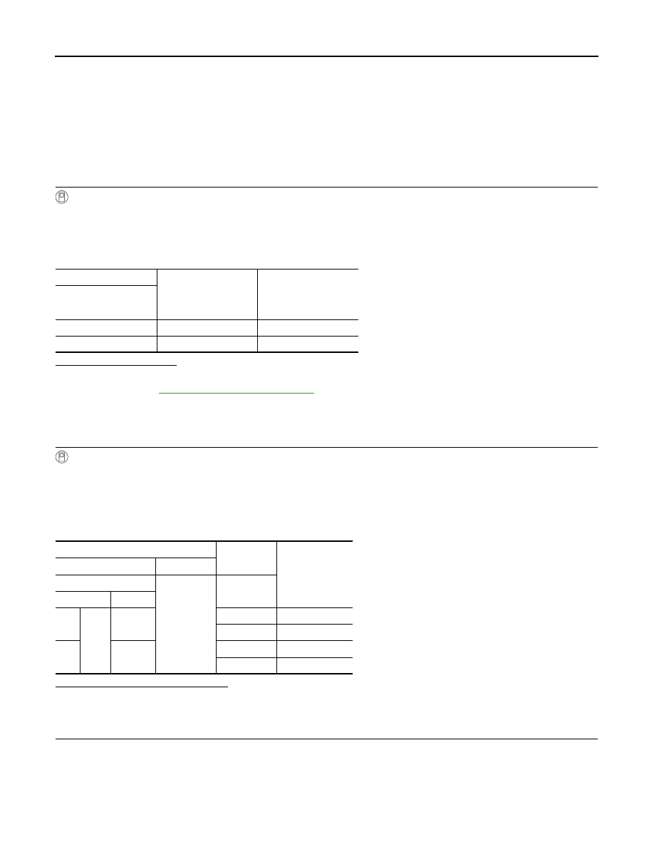
2.
CHECK AIMING MOTOR DRIVE SIGNAL CIRCUIT INPUT
1.
Turn the ignition switch OFF.
2.
Disconnect AFS control unit connector and aiming motor connector.
3.
Check continuity between AFS control unit harness connector and the aiming motor harness connector.
Test item
Light axis angle
(Reference value)
10 m (32.8 ft)-forward
light axis change refer-
ence quantity
(Approx.)
LEVELIZER TEST
Origin
0
°
—
Peak
2.5
°
450 mm (17.9 in)
Terminals
Test item
Voltage
(Approx.)
(+)
(
−
)
AFS control unit
Ground
LEVELIZER
TEST
Connector
Terminal
RH
M16
19
Origin
8.8 V
Peak
1.9 V
LH
40
Origin
8.8 V
Peak
1.9 V
HEADLAMP LEVELIZER CIRCUIT
EXL-71
< COMPONENT DIAGNOSIS >
[XENON TYPE]
C
D
E
F
G
H
I
J
K
M
A
B
EXL
N
O
P
Does continuity exist?
YES
>> Replace the front combination lamp.
NO
>> Repair the harnesses and connectors.
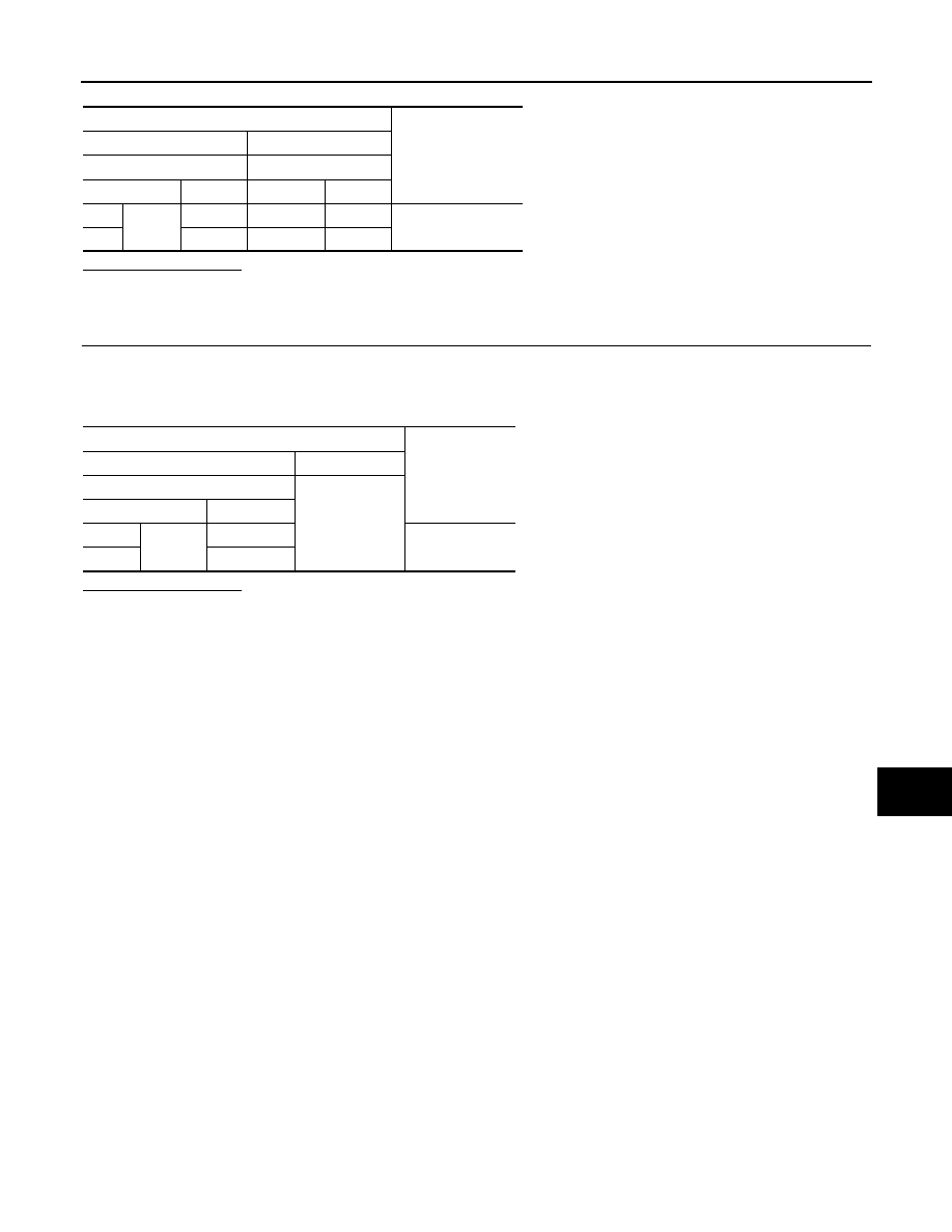
3.
CHECK AIMING MOTOR DRIVE SIGNAL SHORT CIRCUIT
1.
Turn the ignition switch OFF.
2.
Disconnect AFS control unit connector and aiming motor connector.
3.
Check continuity between AFS control unit harness connector and ground.
Does continuity exist?
YES
>> Repair the harness and connectors.
NO
>> Replace AFS control unit.
Terminals
Continuity
(+)
(
−
)
AFS control unit
Aiming motor
Connector
Terminal
Connector
Terminal
RH
M16
19
E26
1
Existed
LH
40
E56
1
Terminals
Continuity
(+)
(
−
)
AFS control unit
Ground
Connector
Terminal
RH
M16
19
Not existed
LH
40
Нет комментариевНе стесняйтесь поделиться с нами вашим ценным мнением.
Текст